


Cable a NIC Access Module
•
•
•
•
•
•
•
•
•
•
•
•
•
•
•
•
•
•
•
•
•
•
•
•
•
•
•
•
•
•
•
•
•
•
•
•
•
•
•
•
•
•
•
•
•
•
•
•
•
•
•
•
•
•
•
•
•
•
JUNOSg 3.0 G10 CMTS Hardware Guide
116
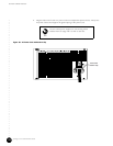
8. If you have reached this step in the procedure, at least five HFC Connector Modules or
SIMs are installed in the G10 CMTS, and a second NIC Access Module and its
corresponding cable are required to complete the interconnection procedure. If
applicable, remove the protective cover that is inserted into the RJ-21 end of the NIC
Access Module cable.
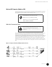
9. Firmly insert the RJ-21 end of the second NIC Access Module cable into the connector
labeled 1 on the NIC Access Module in slot 9 (see Figure 17 on page 49).
10. Tighten the two cable retainer screws by applying 4 in-lb of torque to each of the screws.
11. Locate the PORT 5 and PORT 6 connectors of the NIC Access Module cable and plug
them into the Eth0 and Eth1 ports of the HFC Connector Module or SIM in slot 10. If an
HFC Connector Module or SIM is installed in slot 11, proceed to step 12; otherwise,
proceed to step 15.
12. Locate the PORT 7 and PORT 8 connectors of the NIC Access Module cable and plug
them into the Eth0 and Eth1 ports of the HFC Connector Module or SIM in slot 11. If an
HFC Connector Module or SIM is installed in slot 12, proceed to step 13; otherwise,
proceed to step 15.
13. Locate the PORT 9 and PORT 10 connectors of the NIC Access Module cable and plug
them into the Eth0 and Eth1 ports of the HFC Connector Module or SIM in slot 12. If an
HFC Connector Module or SIM is installed in slot 13, proceed to step 14; otherwise,
proceed to step 15.
14. Locate the PORT 11 and PORT 12 connectors of the NIC Access Module cable and plug
them into the Eth0 and Eth1 ports of the HFC Connector Module or SIM in slot 13.
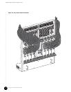
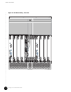
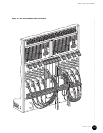
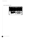
15. Ensure that all the Fast Ethernet ports of the HFC Connector Modules or SIMs are
connected to the NIC Access Modules. Figure 37 on page 117 provides an illustration of
these connections (without the coaxial cables shown).
16. Dress and route all used and unused Ethernet cable wires on all NIC Access Module
cables to avoid obstructing the rear connections of the CMTS.
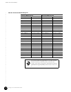
Table 39 on page 118 summarizes the NIC Access Module wiring plan used in this procedure.
The Module – Slot / Port headings specify the HFC Connector Module name, the slot in
which the module is installed, and the Fast Ethernet port label of the module.