


•
•
•
•
•
•
•
•
•
•
•
•
•
•
•
•
•
•
•
•
•
•
•
•
•
•
•
•
•
•
•
•
•
•
•
•
•
•
•
•
•
•
•
•
•
•
•
•
•
•
•
•
•
•
•
•
•
•
Hardware Component Overview
Chassis Control Module
37
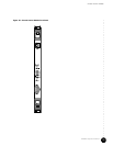
Chassis Control Module
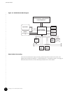
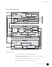
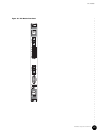
The Chassis Control Module performs management and monitoring functions for the
G10 CMTS, and it provides a single access point for operational and maintenance functions.
In addition, the Chassis Control Module runs the Routing Engine.
The Chassis Control Module connects with the Hard Disk Module in the rear of the chassis
through the midplane. This provides an Ethernet port at the rear of the chassis as well as the
front. See “Hard Disk Module” on page 55 for more discussion.
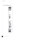
Figure 15 on page 39 shows the Chassis Control Module front panel.
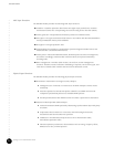
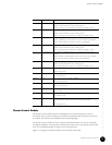
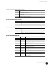
1 Red / Yellow / Green Red—Operating system image loaded for CPU0.
Yellow—Control transferred to CPU0 operating system.
Green—Operating system initialization completed successfully on CPU0.
2 Red / Yellow / Green Red—Operating system image loaded for CPU3.
Yellow—Control transferred to CPU3 operating system.
Green—Operating system initialization completed successfully on CPU3.
3 Red / Yellow / Green Red—Waiting to connect to boot server on Chassis Control Module.
Yellow—Established connection with boot server on Chassis Control Module.
Green—Obtained boot instructions from Chassis Control Module.
4 Red / Yellow / Green Red—Operating system image loaded for CPU2.
Yellow—Control transferred to CPU2 operating system.
Green—Operating system initialization completed successfully on CPU2.
5 Red / Yellow / Green Red—Waiting to establishing link-layer connectivity with Chassis Control
Module.
Yellow—Waiting to establishing IP connectivity with Chassis Control Module.
Green—IP connectivity with Chassis Control Module established.
6 Red / Yellow / Green Red—Operating system image loaded for CPU1.
Yellow—Control transferred to CPU1 operating system.
Green—Operating system initialization completed successfully on CPU1.
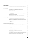
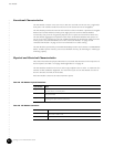
Eth0 Green On—Link is present on traffic port Eth0.
Off—No link present.
Eth1 Green On—Link is present on traffic port Eth1.
Off—No link present.
Activity 0 Green On—Activity is present on traffic port Eth0.
Off—No activity present.
Activity 1 Green On—Activity is present on traffic port Eth1.
Off—No activity present.
Link Green On—Link present.
Off—No link.
10/100 Amber On—100Base-T mode.
Off—10Base-T mode.
Hot Swap Blue ON—Module is ready to be removed. Illuminates after the ejector release is
pressed. During hot insertion, LED is ON until ejectors are locked.
OFF during power up.
LED Label Color Function