


DOCSIS Module
•
•
•
•
•
•
•
•
•
•
•
•
•
•
•
•
•
•
•
•
•
•
•
•
•
•
•
•
•
•
•
•
•
•
•
•
•
•
•
•
•
•
•
•
•
•
•
•
•
•
•
•
•
•
•
•
•
•
JUNOSg 3.0 G10 CMTS Hardware Guide
36
Physical and Electrical Characteristics
This section describes the physical and electrical characteristics of the DOCSIS Module. See
Table 8 through Table 10.
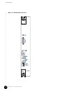
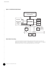
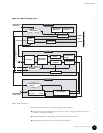
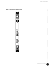
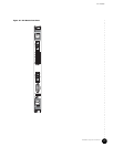
The DOCSIS Module installs into the chassis from the front and spans two midplane
connector columns. The module includes the RF upconverter and modem subassemblies.
The module connects to the midplane through connectors J1 through J5. See “Card Cage and
Midplane” on page 21 for related information.
The front panel connectors are not used.
Each DOCSIS Module with its subassemblies consumes 120 watts maximum power.
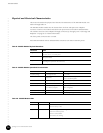
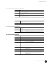
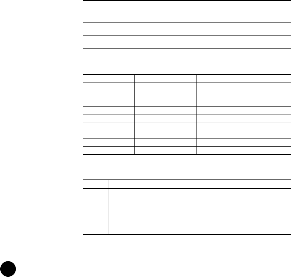
Table 8: DOCSIS Module Physical Dimensions
Table 9: DOCSIS Module Operational Characteristics
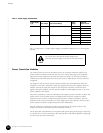
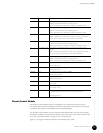
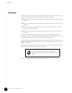
Table 10: DOCSIS Module LEDs
Dimension Value
Height 233 mm (9.2 in.) card
262 mm (10.3 in., 6 U) front panel
Width 40 mm (1.6 in.)
(front panel width)
Depth 340 mm (13.4 in.)
(excluding front panel and cPCI connectors)
Characteristic Downstream Upstream
Frequency Range 91 through 857 MHz 5 – 42 MHz
Power level +50 through +61 dBmV
(adjustable)
+8 to +55 dBmV (16QAM)
+8 to +58 dBmV (QPSK)
Modulation 64QAM and 256QAM QPSK, 16QAM
Transmission protocol DOCSIS MPEG Frequency-agile TDMA
Symbol rate 5.057 Mbaud (64QAM)
5.361 Mbaud (256QAM)
160, 320, 640, 1280, and 2560
(user configurable)
Data rate (Max.) 40 Mbps/interface 10 Mbps/interface
Interfaces 4 8 or 16 (depending on the DOCSIS Module model)
LED Label Color Function
CPCI Green On—cPCI bus is active.
Off—No activity on bus.
Test Green / Red Green Blinking—Self-test running.
Green On—Self-test passed.
Red On—Self-test failed.
Off—Self-test not running.