


7
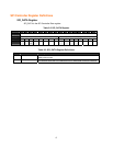
CTL Register
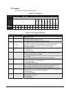
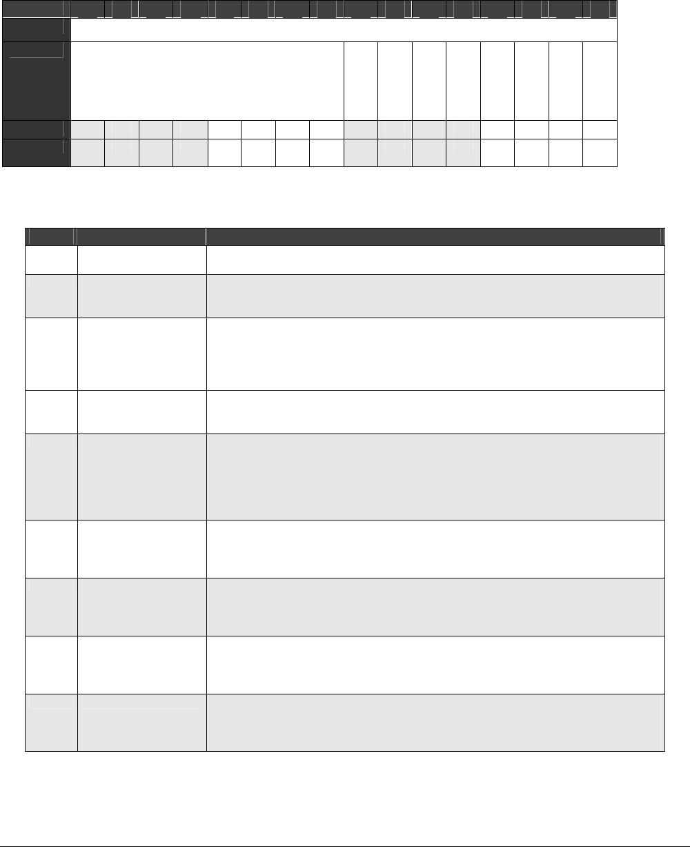
CTL is the SPI Controller Control register.
Table 2-4. CTL Register
BIT
15 14 13 12 11 10 9 8 7 6 5 4 3 2 1 0
OFFSET
B802
FIELD
///
IRQENB
AUTODRV
INVCS
PHASE
CKPOL
WOR
MSTN
ALT
RESET
0 0 0 0 0 0 0 0 0 0 0 0 0 0 0 0
RW RW RW RW RW R
W
RW RW RW RW RW RW RW RW RW RW RW
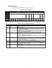
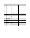
Table 2-5. CTL Register Definitions
Bits Field Name Description
15:8 ///
Reserved
Always returns zero.
7 IRQENB
Interrupt Request Enable
1 = enable the SPI to generate interrupts.
0 = disable the SPI from generating interrupts (default).
6
AUTODRV
Autodrv
1 = enabled. Autodrv generates the sequence of selecting the serial device (CS)
and transferring data to it and then deselecting the device with no CPU
interaction. The transfer is started by writing to the data register.
0 = disabled (default).
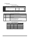
5
INVCS
Invert Chip Select
1 = inverted CS.
0 = normal (default).
4 PHASE
Phase Select
Selects the operating mode for the SPI interface. The two modes select where
the opposite edge D-Flip-Flop is placed.
1 = the negative edge flop is inserted into the shift_out path to hold the data for an
extra ½ clock.
0 = a negative edge flop is inserted into the shift_in path (default).
3 CKPOL
Clock Polarity
Controls the polarity of the SCLK (SPI clock).
1 = SCLK idles HIGH.
0 = SCLK idles LOW (default).
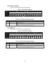
2 WOR
Wire-O
HIGH = WOR bit configures the SPI bus to operate as an Open-Drain. This
prevents SPI bus conflicts when there are multiple bus masters.
LOW = WOR bit does not configure the SPI bus to operate as an Open-Drain.
1 MSTN
Master Enable
Selects master or slave mode for the SPI interface.
1 = master mode.
0 = slave mode (default).
0 ALT
Alternate I/O Pinouts
Enable alternate I/O pinouts.
1 = alternate I/O.
0 = normal (default).