


58
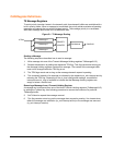
Theory of Operation
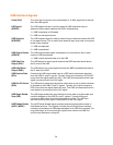
The CAN controller appears to the microprocessor as an I/O device. Each peripheral has 256
bytes of I/O address space allocated to it. CAN0 and CAN1 share Interrupt 6.
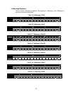
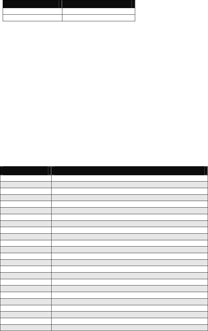
Table 5-2. CAN I/O Address
CAN Controller Base Address
CAN0 A800h
CAN1 A900h
CAN Register Summaries
DSTni contains two independent CAN channels. Operation and access to each device,
however, is the same. The only difference is the starting I/O base address for each channel, as
shown in Table 5-2.
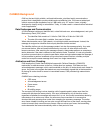
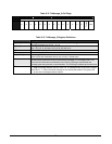
Both CAN channels have their registers located and fixed in the internal I/O space of the DSTni
chip. Both are implemented as true 16-bit devices. Therefore, all accesses made to the CAN
channel registers must be 16-bit I/O-type accesses in the I/O space. Byte accesses result in
erroneous operation.
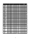
Each CAN channel has 62, 16-bit registers. These registers allow for configuration, control,
status, and operational data. Table 5-3 the 16-bit register mapping for both CAN channels of
these registers. The hex offsets shown in the table are offset from the base addresses in Table
5-2.
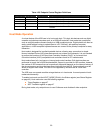
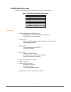
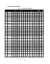
Register Summary
Table 5-3. CAN Channel Register Summary
Hex Offset Register
00 TxMessage_0: ID, ID28-13
02 ID12-00
04 TxMessage_0: Data, D55-48, D63-56
06 D39-32, D47-40
08 D23-16, D31-24
0A D07-00, D15-08
0C TxMessage_0: RTR, IDE, DLC_3-0
0E TxMessage_0: Control Flags, TXAbort, TRX
10 TxMessage_1: ID, ID28-13
12 ID12-00
14 TxMessage_1: Data, D55-48, D63-56
16 D39-32, D47-40
18 D23-16, D31-24
1A D07-00, D15-08
1C TxMessage_1: RTR, IDE, DLC_3-0
1E TxMessage_1: Control Flags, TXAbort, TRX
20 TxMessage_2: ID, ID28-13
22 ID12-00
24 TxMessage_2: Data, D55-48, D63-56
26 D39-32, D47-40
28 D23-16, D31-24
2A D07-00, D15-08
2C TxMessage_2: RTR, IDE, DLC_3-0
2E TxMessage_2: Control Flags, TXAbort, TRX