81
CANbus Analysis
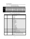
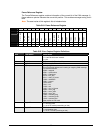
Three additional registers are provided for advanced analysis of a CAN system. These registers
include arbitration lost and error capture registers, as well as a CANbus frame reference
register that contains information about the CANbus state and the physical Rx and TX pins.
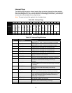
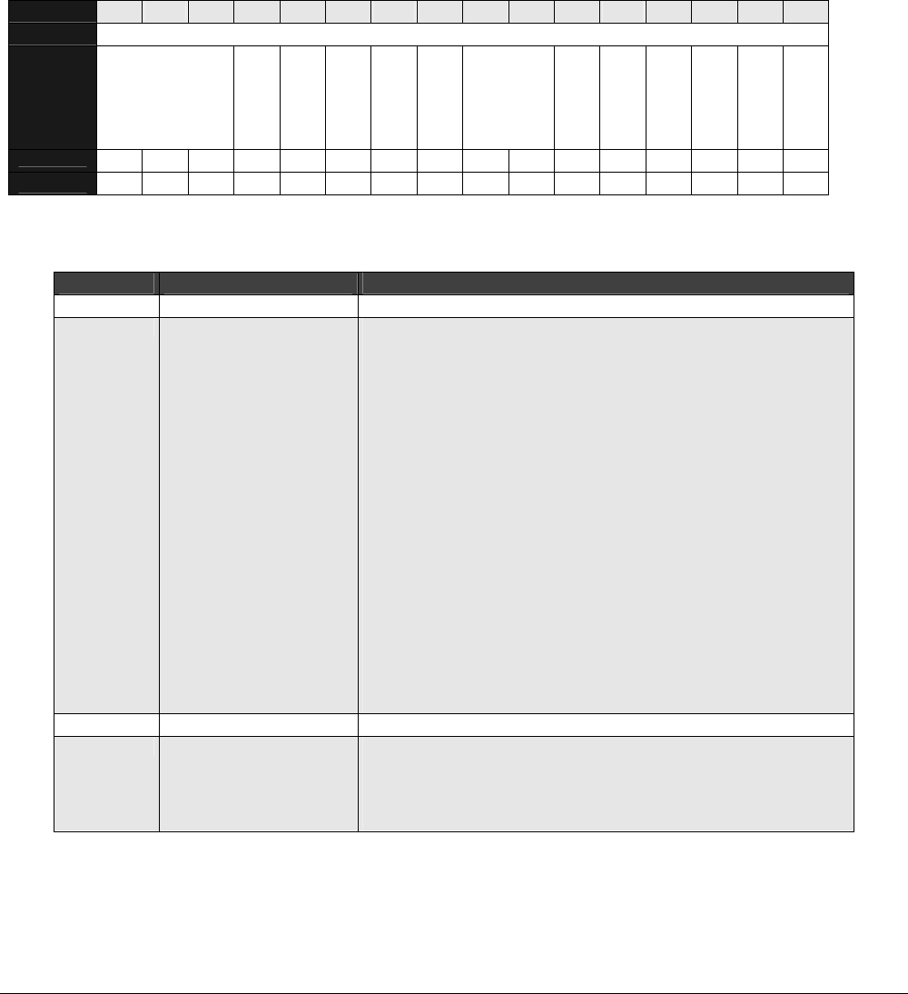
Arbitration Lost Capture Register
The Arbitration Lost Capture register captures the most recent arbitration loss event with the
frame reference pointer.
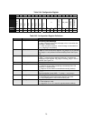
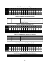
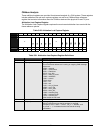
Table 5-60. Arbitration Lost Capture Register
BIT 15 14 13 12 11 10 9 8 7 6 5 4 3 2 1 0
OFFSET 76h
FIELD
///
FR4
FR3
FR2
FR1
FR0
///
FRB5
FRB4
FRB3
FRB2
FRB1
FRB0
RESET 0 0 0 0 0 0 0 0 0 0 0 0 0 0 0 0
R/W R/W R/W R/W R/W R/W R/W R/W R/W R/W R/W R/W R/W R/W R/W R/W R/W
Table 5-61. Arbitration Lost Capture Register Definitions
Bits Field Name Description
15:13 ///
Reserved
12:8 FR[4:0]
frame_ref_Field
This is the frame reference a incoming or outgoing CAN message.
Values are:
00000 = stopped
00001 = synchronize
00101 = interframe
00110 = bus_idle
00111 = start_of_frame
01000 = arbitration
01001 = control
01010= data
01011 = crc
01100 = ack
01101 = end_of_frame
10000 = error_flag
10001 = error_echo
10010 = error_del:
11000 = overload_flag
11001 = overload_echo
11010 = overload_del
Other codes are not used.
7:6 ///
Reserved
5:0 FRB[5:0]
frame_ref_bit_nr
A 6-bit vector that counts the bit numbers in one field.
Example: if field = “data” = “01010”, “bit_nr” = “000000”, and
“tx_mode” = ‘1’, it indicates that the first data bit is being
transmitted.


