


16
Transmitting Each Data Byte
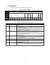
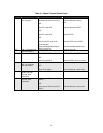
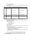
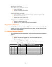
After each data byte transmits, the IFLG is set, and one of the three status codes in Table 3-3 is
in the Status register.
Table 3-3. Status Codes After Each Data Byte Transmits
Code I
2
C State Microprocessor Response Next I
2
C Action
28h Data byte transmitted,
ACK received
Write byte to DAT, clear IFLG
OR
Set STA, clear IFLG
OR
Set STP, clear IFLG
OR
Set STA and STP, clear IFLG
Transmit data byte, receive ACK
Transmit repeated START
Transmit STOP
Transmit START then STOP
30h Data byte transmitted,
ACK not received
Same as code 28h Same as code 28h
38h Arbitration lost Clear IFLG
OR
Set STA, clear IFLG
Return to idle
Transmit START when bus free
All Bytes Transmit Completely
When all bytes transmit completely, set the STP bit by writing a 1 to this bit in the Control
register. The I
2
C controller:
Transmits a STOP condition
Clears the STP bit
Returns to the idle state
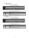
Master Receive Mode
In master receive mode, the I
2
C controller receives a number of bytes from a slave transmitter.
After the START condition transmits:
1. The IFLG bit is set and status code 08h is in the Status register.
2. The Data register has the slave address (or the first part of a 10-bit slave address), with the
least-significant bits set to 1 to signify a read.
3. The IFLG bit is 0 and prompts the transfer to continue.
4. When the 7-bit slave address (or the first part of a 10-bit address) and the read bit transmit,
the IFLG bit is set again.
A number of status codes are possible in the Status register, as shown in Table 3-4.
Note: In 10-bit addressing, after the first part of a 10-bit address and the read bit successfully
transmit, the status code is 40h or 48h. If a repeated START condition transmits, the status
code is 10h instead of 08h.