


84
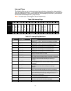
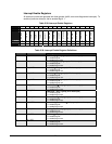
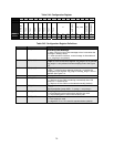
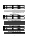
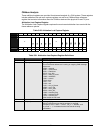
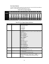
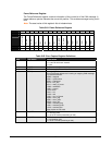
Bits Field Name Description
5:0 FRB[5:0]
frame_ref_bit_nr
A 6-bit vector that counts the bit numbers in one field.
Example: if field = “data” = “01010”, “bit_nr” = “000000”, and
“tx_mode” = ‘1’, it indicates that the first data bit is being
transmitted.
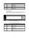
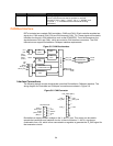
CAN Bus Interface
DSTni contains two complete CAN controllers, CAN0 and CAN1. Each controller supplies two
signal pins, CAN receive (CAN_RX) and CAN transmit (CAN_TX). These signals are routed to
interface circuits and a CAN transceiver such as the PCA82C251. From the transceiver, the
signals become CAN- and CAN+, which are routed to CAN interface connectors. The CAN
transceiver can support DeviceNet or CANopen interface requirements.
Figure 5-5. CAN Bus Interface
Acceptance
Filters
RX
FIFO
TX
FIFO
INT
CTRL
STATUS &
CONFIGURATION
START/STOP
CTRL
BUS COUPLER
CLK
RST
PCS1
(CAN0)
PCS2
(CAN1)
RD
WR
ADDR
DATA_IN
DATA_OUT
CAN_RX
CAN_TX
INT1 (CAN0)
INT2 (CAN1)
CAN MODULE
CANBUS
TRANSCEIVER
CANL
CANH
82C251
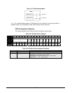
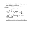
Interface Connections
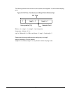
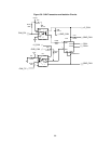
The following sample circuits demonstrate a practical DeviceNet or CANopen interface. The
wiring diagram for DeviceNet and CANopen connections are shown in Figure 5-6.
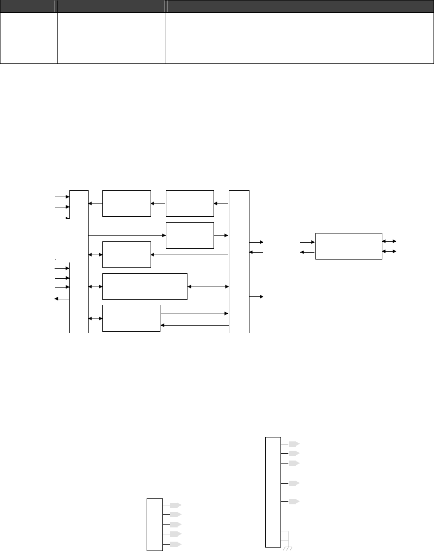
Figure 5-6. CAN Connector
1V-
2
CAN+
3SHIELD
4
CAN-
5V+
(BLK) V-
(WHT) CAN+
Shield
(BLU) CAN-
(RED) V+
DeviceNet CAN
1
2
CAN+
3GND_CAN
4
CAN-
5
CAN_H
CAN_GND
CAN_L
6
7
8
9
10
11
CAN_OPEN (DB-9)
DeviceNet can supply network voltage on the V- and V+ pins. This supply can be used to
operate the transceiver and interface circuits. In the circuit below, V- and V+ signals are
combined to form +24, which is then connected to a regulator to generate the +5_BUS signal for
the transceiver circuits.
CAN0
CAN1
INT6
INT6