


70
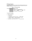
Error Count and Status Registers
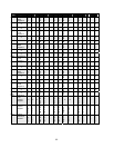
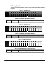
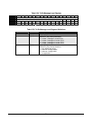
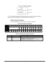
Table 5-30. Tx/Rx Error Count
BIT 15 14 13 12 11 10 9 8 7 6 5 4 3 2 1 0
OFFSET 40h
FIELD RE7 RE6 RE5 RE4 RE3 RE2 RE1 RE0 TE7 TE6 TE5 TE4 TE3 TE2 TE1 TE0
RESET 0 0 0 0 0 0 0 0 0 0 0 0 0 0 0 0
R/W R/W R/W R/W R/W R/W R/W R/W R/W R/W R/W R/W R/W R/W R/W R/W R/W
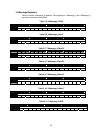
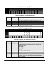
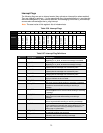
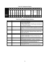
Table 5-31. Tx\Rx Error Count Register Definitions
Bits Field Name Description
15:8 RE[7:0]
Rx_er_cnt Bits
The receiver error counter according to the Bosch CAN specification. When
in bus off, this counter counts the idle states.
7:0 TE[7:0]
Tx_er_cnt Bits
The transmitter error counter according to the Bosch CAN specification.
When it is greater than 255 (dec), it is fixed at 255.
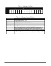
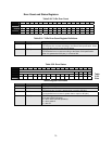
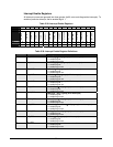
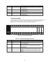
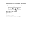
Table 5-32. Error Status
Table
5-33.
Error
Status Register Definitions
Bits Field Name Description
15:4 ///
Reserved
3 RX96
Rxgte96 or rx > 96
The receiver error counter is greater than or equal to 96 (dec).
2 TX96
Tx96 or tx > 96
The transmitter error counter is greater than or equal to 96 (dec).
1:0 ES[1:0]
ES1-0 Error_stat
Error state of the CAN node:
00 = error active (normal operation).
01 = error passive.
1x = bus off.
BIT 15 14 13 12 11 10 9 8 7 6 5 4 3 2 1 0
OFFSET 42h
FIELD /// RX96 TX96 ES1 ES0
RESET 0 0 0 0 0 0 0 0 0 0 0 0 0 0 0 0
R/W R R R R R R R R R R R R R R R R