21
Bus Clock Considerations
Bus Clock Speed
The I
2
C bus can be defined for bus clock speeds up to 100 Kb/s and up to 400 Kb/s in fast
mode.
To detect START and STOP conditions on the bus, the M I
2
C must sample the I
2
C bus at least
10 times faster than the fastest master bus clock on the bus. The sampling frequency must be
at least 1 MHz (4 MHz in fast-mode) to guarantee correct operation with other bus masters.
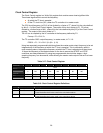
The CLK input clock frequency and the value in CCR bits 2 - 0 determine the I
2
C sampling
frequency. When the I
2
C controller is in the master mode, it determines the frequency of the
CLK input and the values in bits [2:0] and [6:3] of the Clock Control register (see Clock Control
Register on page 28).
Clock Synchronization
If another device on the I
2
C bus drives the clock line when the I
2
C controller is in master mode,
the I
2
C controller synchronizes its clock to the I
2
C bus clock.
The device that generates the shortest high clock period determines the high period of
the clock.
The device that generates the longest LOW clock period determines the LOW period of
the clock.
When the I
2
C controller is in master mode and is communicating with a slow slave, the slave
can stretch each bit period by holding the SCL line LOW until it is ready for the next bit. When
the I
2
C controller is in slave mode, it holds the SCL line LOW after each byte transfers until the
IFLG clears in the Control register.
Bus Arbitration
In master mode, the I
2
C controller checks that each logical 1 transmitted appears on the I
2
C bus
as a logical 1. If another device on the bus overrules and pulls the SDA line LOW, arbitration is
lost.
If arbitration is lost:
While a data byte or Not-Acknowledge bit is being transmitted, the I
2
C controller returns
to the idle state.
During the transmission of an address, the I
2
C controller switches to slave mode so that
it can recognize its own slave address or the general call address.


