36
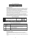
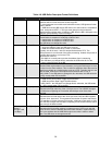
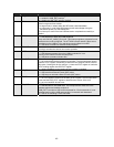
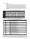
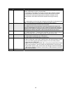
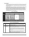
Table 4-6. USB Buffer Descriptor Format Definitions
Bits Field Name Description
7 OWN
BD Owner
Specifies which unit has exclusive access to the BD.
0 = microprocessor has exclusive and entire BD access; USB ignores all other
fields in the BD
1 = USB has exclusive BD access SIE writes a 0 to this bit when it completes a
token, except when KEEP=1. This byte must always be the last byte the
microprocessor updates when it initializes a BD. After the BD is assigned to the
USB, the microprocessor must not change it.
6 DATA0/1
DATA0/1 Transmit or Receive
Transmission or reception of a DATA0 or DATA1 field.
0 = transmission or reception of a DATA0 field.
1 = transmission or reception of a DATA1 field.
The USB does not change this value.
5 USB_OWN
USB Ownership
1 = once the OWN bit is set, the USB owns it forever.
0 = USB can release the BD when a token is processed.
Typically, this bit is set to 1 with ISO endpoints that feed a FIFO. The
microprocessor is not informed of the token processing. Instead, the process is
a simple data transfer to or from the FIFO.
When this bit is set to1:
• The NINC bit is usually set to prevent the address from incrementing.
• The USB does not change this bit; otherwise the USB writes bit 3 of the
current token PID back to the BD.
4 NINC
No Increment Bit
Disables DMA engine address incrementation, forcing the DMA engine to read
or write from the same address. This is useful for endpoints when data must be
read from or written to a single location such as a FIFO. Typically, this bit is set
with the USB_OWN bit for ISO endpoints that interface with a FIFO. If
USB_OWN=1, the USB does not change this bit; otherwise, the USB writes bit
2 of the current token PID to the BD.
3 DTS
Data Toggle Synchronization
0 = USB cannot perform Data Toggle Synchronization.
1 = USB can perform Data Toggle Synchronization.
If USB_OWN=1, the USB does not change this bit; otherwise, the USB writes
bit 1 of the current token PID to the BD.
1:0 BCH[9:8]
Byte Count High Bits
Represent the high-order bits of the 10-bit byte count. The USB SIE changes
this field after completing an RX transfer with the byte count of the data
received.
7:0 BCL
Byte Count Low Bits
Represent the low-order byte of the 10-bit byte count. BCH and BCL together
form the 10-bit byte count. This represents the number of bytes to transmit for
a TX transfer or receive during an RX transfer. Valid byte counts are 0 to 1023.
The USB SIE changes this field after completing an RX transfer with the actual
byte count of the data received.
7:0
(Bytes 4
through 2 and
Low Byte)
ADDR[31:0]
Address Bits
Represent the 32-bit buffer address in system memory. DSTni only uses the
lower 24 bits to form the address where the buffer resides in system memory.
This is the address that the USB DMA engine uses when it reads or writes
data. The USB does not change these bits.


