42
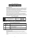
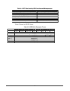
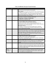
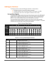
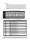
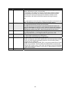
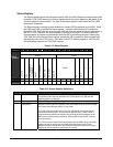
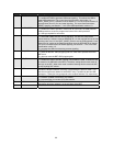
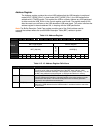
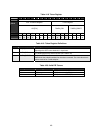
Bits Field Name Description
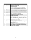
5 DMAERR 1 = USB requests a DMA access to read a new BDT, but is not given the bus
before USB needs to receive or transmit data.
• If processing a TX transfer, this causes a transmit data underflow condition.
• If processing an Rx transfer, this causes a receive data overflow condition.
This interrupt is useful for developing device-arbitration hardware for the
microprocessor and USB to minimize bus request and bus grant latency.
OR
1 = a data packet to or from the host is larger than the buffer size allocated in the
BDT. The data packet is truncated as it is placed into buffer memory.
4 BTOERR 1 = a bus turnaround time-out error occurred.
0 = a bus turnaround time-out error has not occurred.
The USB uses a bus-turnaround timer to track the elapsed time between the
token and data phases of a SETUP or OUT TOKEN or the data and handshake
phases of a IN TOKEN. If more that 16-bit times are counted from the previous
EOP before a transition from IDLE, a bus turnaround time-out error occurs.
3 DFN8
Data Field Received Not 8 Bits
The USB Specification 1.0 states that the data field must be an integral number of
bytes. If the data field is not an integral number of bytes, this bit is set.
2 CRC16
CRC16 Failure
1 = data packet is rejected due to a CRC16 error.
0 = data packet is not rejected due to a CRC16 error.
1 CRC5\EOF
Error interrupt with two functions.
• USB is in peripheral mode (HOST_MODE_EN=0): this interrupt detects a CRC5
error in the token packets generated by the host. If set, the token packet is
rejected due to a CRC5 error.
• USB is in host mode (HOST_MODE_EN=1): this interrupt detects End-of-Frame
(EOF) error conditions. This occurs when the USB transmits or receives data
and the SOF counter is zero. In this mode, this interrupt is useful for developing
USB packet-scheduling software to ensure that no USB transactions cross the
start of the next frame.
0 PID_ERR
PID check field failed.


