12
Block Diagram
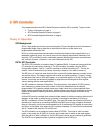
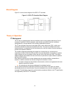
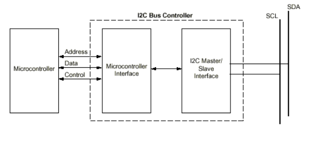
Figure 3-1 shows a block diagram of the DSTni I
2
C controller.
Figure 3-1. DSTni I
2
C Controller Block Diagram
Theory of Operation
I
2
C Background
The I
2
C bus is a popular serial, two-wire interface used in many systems because of its low
overhead. Capable of 100 KHz operation, each device connected to the bus is software
addressable by a unique address, with a simple master/slave protocol.
The I
2
C bus consists of two wires, serial data (SDA), and a serial clock (SCL), which carry
information between the devices connected to the bus. This two-wire interface minimizes
interconnections, so integrated circuits have fewer pins, and the number of traces required on
printed circuit boards is reduced.
The number of devices connected to the same bus is limited only by a maximum bus
capacitance of 400 pF. Both the SDA and SCL lines are bidirectional, connected to a positive
supply voltage via a pull-up resistor. When the bus is free, both lines are HIGH. The output
stages of devices connected to the bus must have an open-drain or open-collector to perform
the wired-AND function.
Each device on the bus has a unique address and can operate as either a transmitter or
receiver. In addition, devices can also be configured as masters or slaves.
A master is the device that initiates a data transfer on the bus and generates the clock
signals to permit that transfer.
Any other device that is being addressed is considered a slave.
The I
2
C protocol defines an arbitration procedure to ensure that if more than one master
simultaneously tries to control the bus, only one is allowed to do so and the message is not
corrupted. The arbitration and clock synchronization procedures defined in the I
2
C specification
are supported by the DSTni I
2
C controller.


