


85
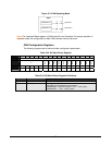
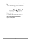
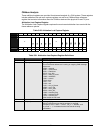
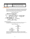
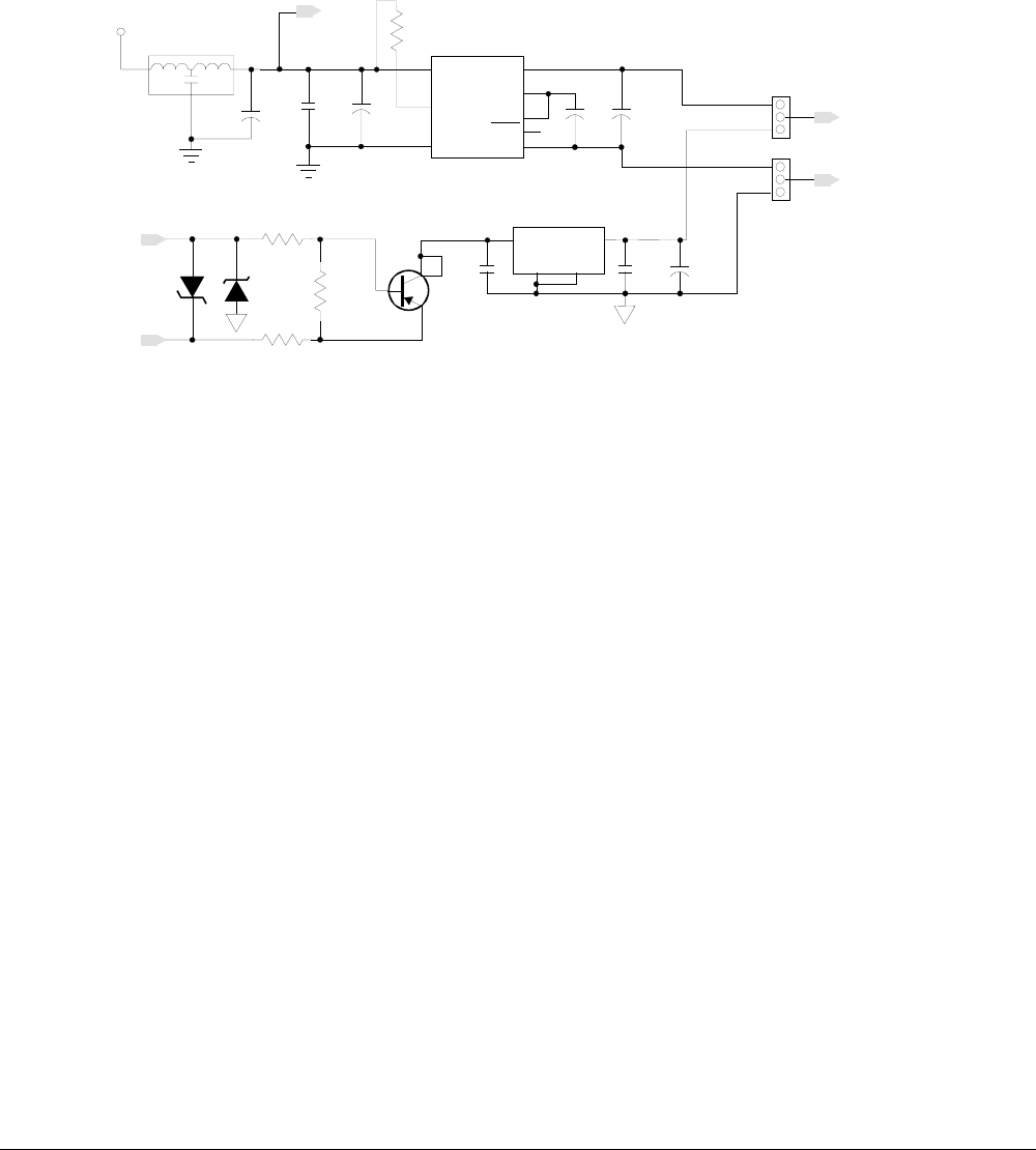
You can also provide local isolated power for the transceiver circuits, as required when using
CANopen. If you are using both DeviceNet and CANopen, use the jumpers to select between
bus power (+5_BUS) or isolated power (ISO_PWR). The jumpers P_C05V and P_C0G will then
provide +5_CAN and GND_CAN to the transceiver circuits.
Note: Diagrams are for tutorial purposes only and may not reflect the actual circuit on the
evaluation module. Always refer to the reference schematic diagrams included with the
evaluation module.
Figure 5-7. Power for CAN
2
+5_CAN
GND_CAN
C18
0.1uf
+VIN
1
-IN
17
U7
DC-DC5V
VOUT
VREC
ENA
-VOUT
8
11
C72
1uf
+
7
9
ISO_PWR
31
2
C17
10uf
+
1
2
+5V
L1
NFM61R30T472T1
SYNC
18
C112
10uf
+
1
2
R108
1.K
ERR
12
C13
10uf
+
1
2
V-
V+
Z1
D1
P4KE33CA
SB160
R11
3.9K
R10
R9
1.5K
PZT2907AT1
Q1
+24V
1
3
2,4
I
C2
0.1uf
U14
IN
OUT
GND GND
LM2940IMP-5.0
1 3
24
C1
0.1uf
C3
22uf
+
+5_BUS
1
3
2
1
3
P_C05V
P_C0G
P_C05V and P_C0G Pos 1-2
for Isolated Power.
P_C05V and P_C0G Pos 2-3
for BUS Power.
F5V
3.9
I
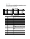
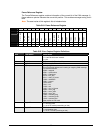
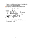
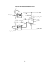
The transceiver converts CAN- and CAN+ signals to RXD and TXD signals and vice versa. To
protect DSTni from external electrical noise, the CAN interface circuits are isolated. The
following circuits show how the RXD and TXD signals from the transceiver are isolated from the
DSTni CAN_RX and CAN_TX signals.