


25
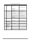
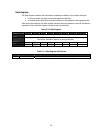
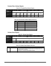
Control Register
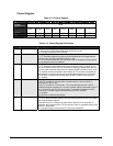
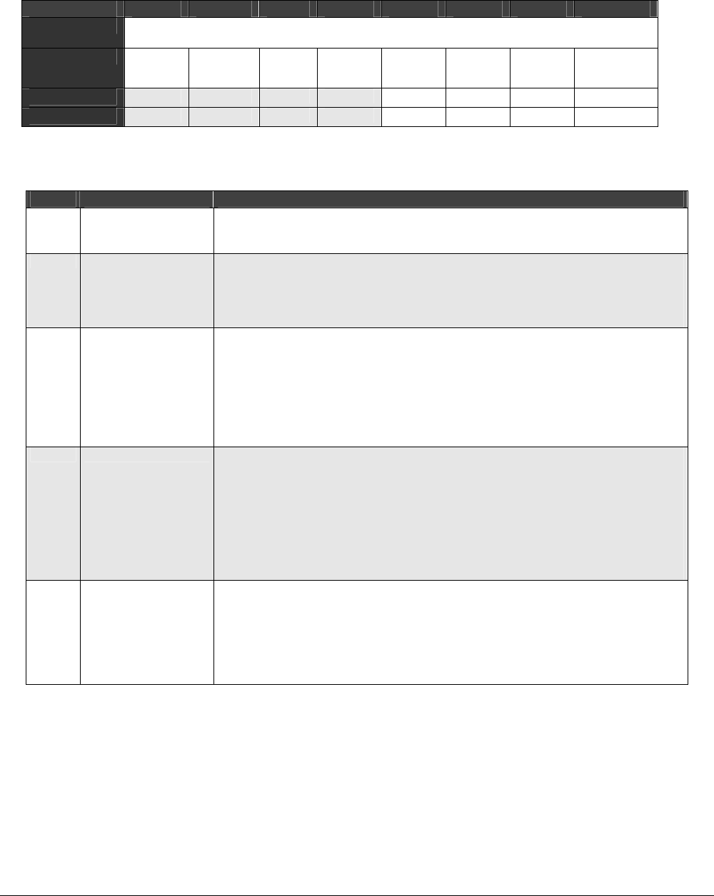
Table 3-12. Control Register
BIT 7 6 5 4 3 2 1 0
OFFSET
D004
FIELD
IEN ENAB STA STP IFLG AAK /// ///
RESET
0 0 0 0 0 0 0 0
RW
RW RW RW RW RW RW RW RW
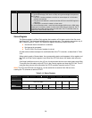
Table 3-13. Control Register Definitions
Bits Field Name Description
7 IEN
Extended Slave Address
l = interrupt line (INTR) goes HIGH when the IFLG bit is set.
0 = interrupt line remains LOW (default).
6 ENAB
Extended Slave Address
1 = I
2
C Controller responds to calls to its slave address and to the general call
address if the GCE bit in the ADDR register is set.
0 = I
2
C bus inputs ISDA/ISCL are ignored and the I
2
C controller will not respond
to any address on the bus (default).
5 STA
Start Condition
1 = I
2
C controller enters master mode and transmits a START condition on the
bus when the bus is free. If the I
2
C controller is already in master mode and one
or more bytes have been transmitted, a repeated START condition is sent. If the
I
2
C controller is being accessed in slave mode, the I
2
C controller completes the
data transfer in slave mode and enters master mode when the bus is released.
The STA bit is cleared automatically after a START condition has been sent.
0 = no effect.
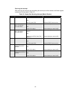
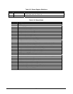
4 STP
Stop Condition
1 and I
2
C controller is in slave mode in master mode = a stop condition is
transmitted on the I
2
C bus.
0 and I
2
C controller is in slave mode = I
2
C controller behaves as if a STOP
condition has been received, but no STOP condition will be transmitted on the I
2
C
bus. If both STA and STP bits are set, the I
2
C controller transmits the STOP
condition (if in master mode), then transmits the START condition.
0 = no effect.
The STP bit is cleared automatically.
3 IFLG
I
2
C State
1 = an I
2
C state has been entered. The only state that does not set IFLG is state
F8h. See the Status register.
1 and IEN bit is set = interrupt line goes HIGH. When IFLG is set by the I
2
C
controller, the low period of the I
2
C bus clock line (SCL) is stretched and the data
transfer is suspended.
0 = interrupt line goes LOW and the I
2
C clock line is released.