74
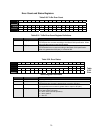
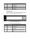
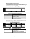
Bits Field Name Description
3 OVR_LOAD
Overload Condition− int3n group (diagnostic interrupts)
1 = enable flag set.
0 = enable flag not set.
2 ARB_LOSS
Arbitration Loss− int3n group (diagnostic interrupts)
1 = enable flag set.
0 = enable flag not set.
1 ///
Reserved
0 INT_ENB
General Interrupt Enable
1 = enable flag set.
0 = enable flag not set.
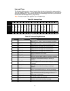
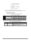
CAN Operating Mode
The CAN modules can be used in different operating modes. By disabling transmitting data, it is
possible to us the CAN in listen only mode enabling features such as automatic bit rate
detection. The two modules can be used in an on-chip loop-back mode.
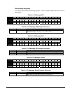
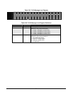
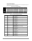
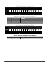
Table 5-40. Interrupt Enable Registers
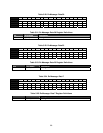
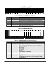
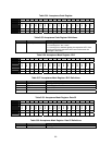
Table 5-41. Interrupt Enable Register Definitions
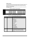
Bits Field Name Description
15:3 ///
Reserved
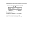
2 LOOP_BACK
Internal Loopback Mode
1 = a-c Internal loopback.
0 = a-b; c-d (default)
1 PASSIVE
Active/Passive
Output is held at ‘ R’ level. The CAN module is only listening.
1 = CAN is passive.
0 = CAN is active.
0 RUN
Run Mode
1 = places the CAN controller in run mode. Reads ‘ 1’ when
running .
0 = places the CAN controller in stop mode. Reads ‘ 0’ when
stopped.
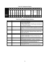
BIT 15 14 13 12 11 10 9 8 7 6 5 4 3 2 1 0
OFFSET 4Ah
FIELD
///
LOOP_BACK
PASSIVE
RUN
RESET 0 0 0 0 0 0 0 0 0 0 0 0 0 0 0 0
R/W R/W R/W R/W R/W R/W R/W R/W R/W R/W R/W R/W R/W R/W R/W R/W R/W


