Removing the system board
To remove the system board, complete the following steps.
1. Read the safety information that begins on page vii and “Installation guidelines”
on page 73.
2. Turn off the server and all attached devices; then, disconnect all power cords
and external cables.
3. Turn the server on its side so that it is lying flat, with the cover facing up.
4. Unlock and remove the side cover (see “Removing the side cover” on page
78).
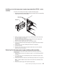
5. Rotate the power-supply cage assembly out of the chassis:
v Hot-swap models:
a. Remove the hot-swap power-supply. Press down on the orange release
lever and pull the power supply out of the bay, using the handle.
b. Lift up the power-supply cage handle and pull the power-supply cage
assembly all the way up until the retainer latch locks the cage in place
on the chassis.
v Non-hot-swap models, lift up the power-supply cage handle and pull the
power-supply cage assembly all the way up until the retainer latch locks the
cage in place on the chassis.
6. Remove the front fan-cage assembly (see “Removing the front system fan
cage assembly” on page 108.
7. Note where each cable is connected; then, disconnect all cables from the
system board.
8. Remove any of the following components that are installed on the system
board and put them in a safe, static-protective place:
v Adapters (see “Removing an adapter” on page 81).
v Microprocessor and heat sink (see “Removing the microprocessor and heat
sink” on page 137).
v DIMMs (see “Removing a memory module” on page 97).
Note: If you replace the system board and need to remove the DIMM
thermal baffles from the non-functional DIMM connectors 3, 6, 9, and 12,
use a pointing object and align it through the holes on the end of the DIMM
thermal baffles and press down on the release clip to release the thermal
baffles.
v Battery (see “Removing the battery” on page 114).
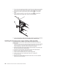
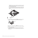
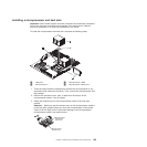
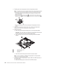
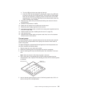
9. Rotate the rear system fan air baffle up out of the way by grasping the tab and
pulling the baffle all the way up; then, slide it outward over the rear of the
server until it locks in place.
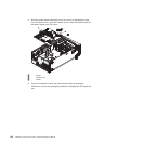
10. Rotate the system board retention latch toward the rear of the chassis.
Chapter 4. Removing and replacing server components 143


