Chapter 2 - Setting Up Your System Hardware
© Polycom, Inc. 2-19
To connect an additional PowerCam:
Be sure to remove the packaging collar from around the camera before powering on the
system.
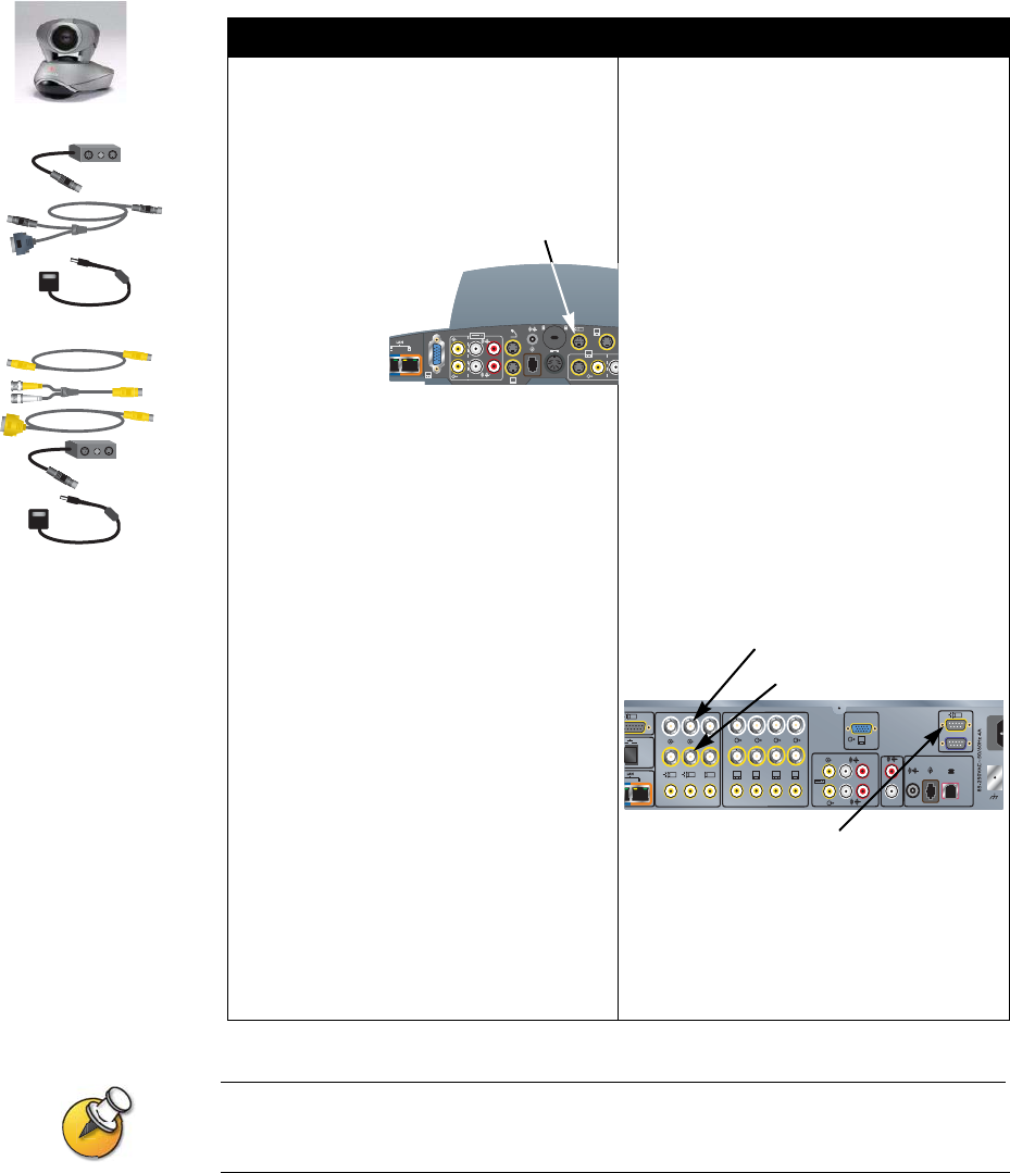
To a ViewStation FX system: To a VS4000 system:
1. Connect the break-out cable to the
PowerCam.
2. Connect the 7-pin connector end of the
Y-shaped PTZ cable to the camera 4
port on the rear panel of the system.
3. Connect the PTZ cable’s 8-pin VISCA
connector to the 8-pin mini-DIN
connector on the left side of the
break-out cable’s connector block.
4. Connect the PTZ cable’s 4-pin S-video
connector to the 4-pin mini-DIN
connector on the right side of the
break-out cable’s connector block.
5. Connect the camera’s power pack to the
center connector on the break-out
cable’s connector block, and to the
appropriate power cord.
6. Connect the power cord to a power
outlet.
1. Connect the break-out cable to the
PowerCam.
2. Connect a mini-DIN to DB-9 VISCA
cable from the system’s camera 4
control connector to the 8-pin mini-DIN
connector on the left side of the
break-out cable’s connector block.
3. Original VS4000:Connect an S-video
cable to the 4-pin mini-DIN connector on
the right side of the break-out cable’s
connector block, and to the Camera 4
S-video connector on the system.
Enhanced VS4000: Connect an
S-video cable to the 4-pin mini-DIN
connector on the right side of the
break-out cable’s connector block, and
to an S-video to BNC adapter.
Connect the adapter’s yellow BNC
connector to the camera 4 C connector,
and the white connector to the camera 4
Y connector on the VS4000 system’s
rear panel.
4. Connect the camera’s power pack to the
center connector on the break-out
cable’s connector block, and to the
appropriate power cord.
5. Connect the power cord to a power
outlet.
Original VS4000
Enhanced VS4000
2
3.3V
12V 3A
7A
2
4
XVGA
1
3
4
Camera 4
2
4
1
4321
3
5
XVGA
4
0101
1
Y
C
Y
C
Camera 4 Control
Camera 4 Y
Camera 4 C


