


4 Replacement Procedures 4.28 TFT FL (Model 14.1 XGA LG. Philips LP141X7-C1TO)
4-92 Satellite Pro M10 Series Maintenance Manual (960-431)
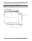
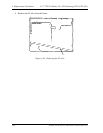
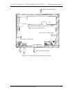
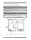
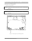
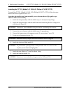
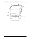
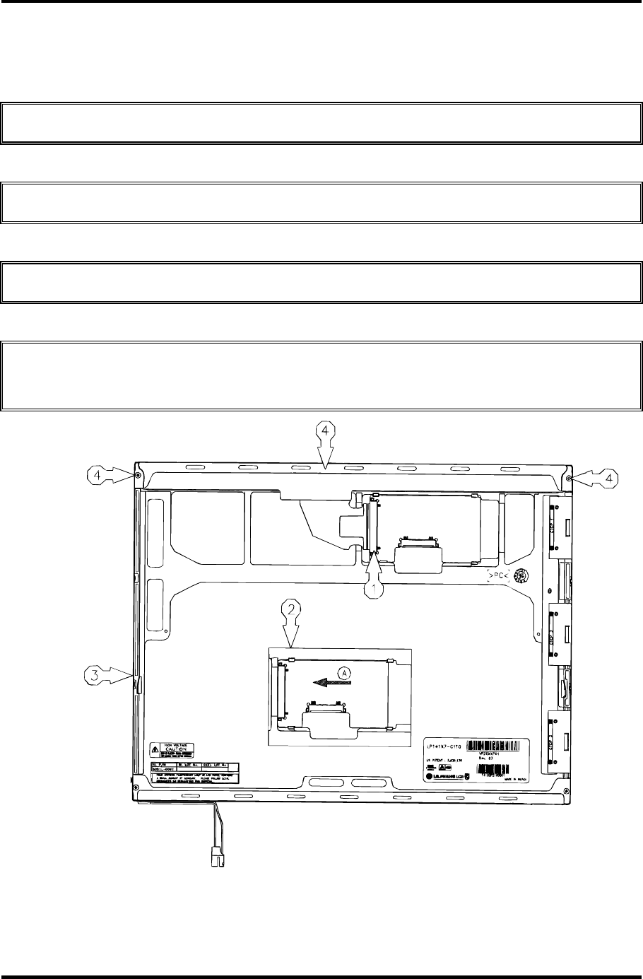
Removing the control PCB, top case and cover assembly
6. Remove the FPC cable (1) used for the control PCB connecting.
CAUTION: Pressure or stress should not be given on the FPC cable.
7. Remove the control PCB (2).
CAUTION: At first, move the control PCB to the left
8. Remove the top case (3)
CAUTION: Pressure or stress should not be given on the top case and gate TCP
9. Remove the screw and cover assembly (4).
CAUTION: Pressure or stress should not be given on the source TCP
Maximum value of torque with screw should be below 2.0kgf.cm
Cover Assembly:3551L-0027A
Screw:1STZL-0001H
Screw:1STZL-0001H
Control PCB:6870L-C017
Case Assembly:
3111L-00070A
Figure 4-66 Removing the control PCB, top case and cover assembly