


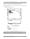


4.34 TFT FL (Model 15.0 UXGA SHARP LQ150U1LW13) 4 Replacement Procedures
Satellite Pro M10 Series Maintenance Manual (960-431) 4-163
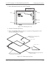
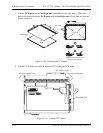
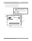
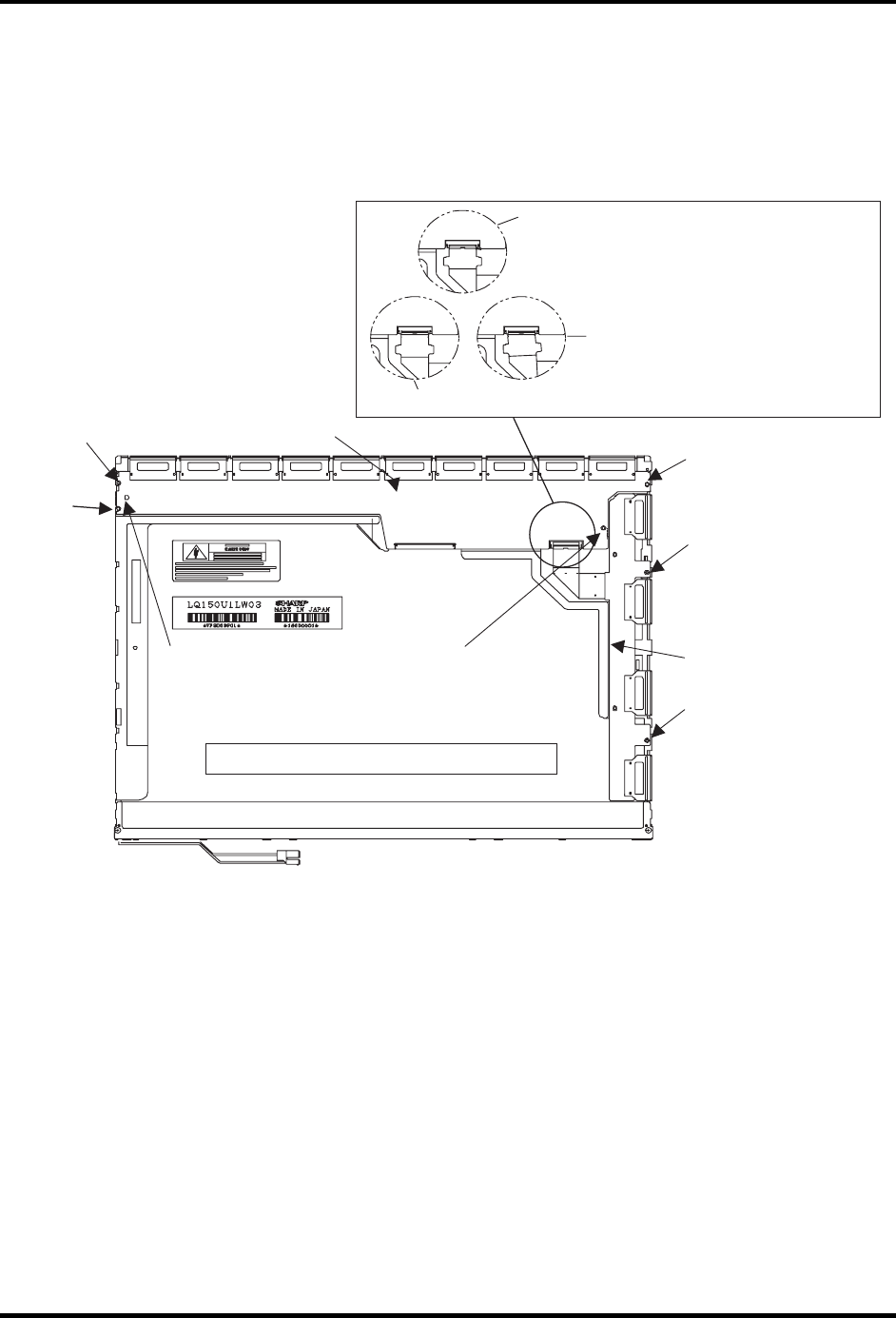
7. Secure the TCP of the source PCB with three screws.
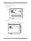
8. Secure the TCP of the gate PCB with two screws.
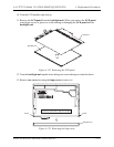
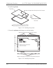
9. Connect the FPC to the connector on the source PCB.
Screw
Screw
Pin*
Pin*
Screw
Screw
Screw
Tighten the screws with 1.0 kgf•cm of torque.
* Align the holes on the PCBs with the pins.
Gate PCB
Source PCB
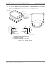
Make sure the latch secures the connector correctly.
See the notches on both the edge of the FPC, and
see the contour of the connector.
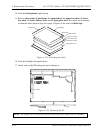
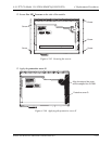
Insert the FPC into the connector firmly. The FPC
must have no inclination. Lock the connector firmly.
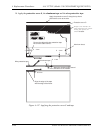
NG: The FPC has inclination.
NG: The FPC does not connect firmly.
Figure 4-142 Securing the TCPs and connecting the FPC