


2 Troubleshooting Procedures 2.8 Display Troubleshooting
2-42 Satellite Pro M10 Series Maintenance Manual (960-431)
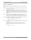
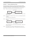
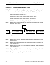
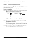
Procedure 3 Connector and Replacement Check
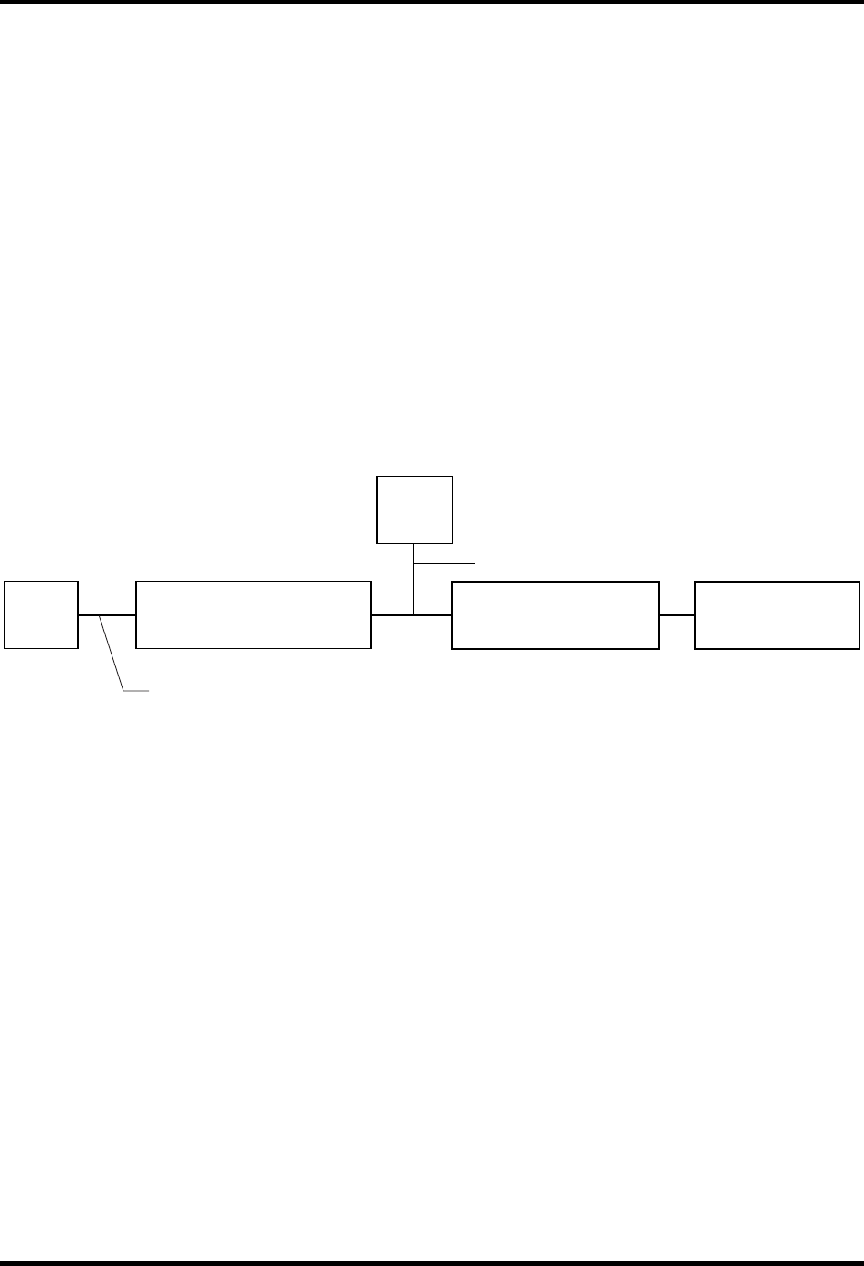
The FL, FL inverter board, LCD module, and system board are connected to the display circuits.
Any of these components may be damaged. Refer to Chapter 4, Replacement Procedures, for
instructions on how to disassemble the computer and then perform the following checks:
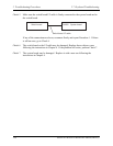
If the FL does not light, perform Check 1.
If characters or graphics are not displayed clearly, perform Check 3.
If some screen functions do not operate properly, perform Check3.
If the FL remains lit when the display is closed, perform Check4.
Check 1 Replace the FL inverter board with a new one and test display again. If the problem
still exists, perform Check 2.
FL
CN1
HV cable
CN2
LCD
LCD/FL cable
PJ4205
VGA board
FL inverter Board
PJ5500
PJ100
System board
Check 2 Replace the FL with a new one and test the display again. If the problem still exists,
perform Check3.
Check 3 Replace the LCD module with a new one and test display again. If the problem still
exists, perform Check 4.
Check 4 Replace the LCD/FL cable with a new one and test display again. If the problem still
exists, perform Check 5.
Check 5 Replace the VGA board with a new one and test display again. If the problem still
exists, perform Check 6.
Check 6 The system board may be damaged. Replace it with a new one.