


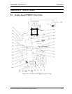
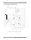
Appendices Appendix B Board Layout
B-2 Satellite Pro M10 Series Maintenance Manual (960-431)
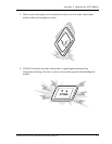
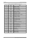
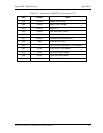
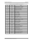
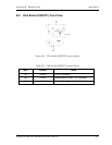
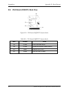
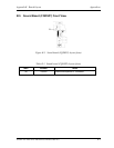
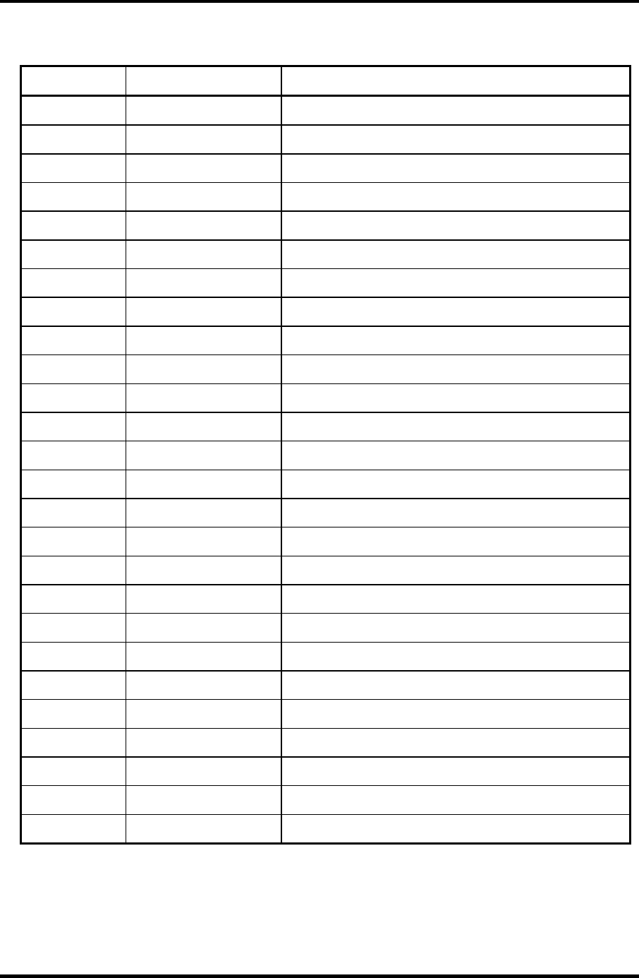
Table B-1 System board (FQDSY*) layout (front) (1/2)
Mark Number Name
(A) PJ123 Keyboard I/F Connector
(B) PJ326 Debug Port I/F Connector
(C) PJ2003 Touch Pad I/F Connector
(D) PJ2015 Mini PCI Card I/F Connector
(E) PJ2025 Switch Board (FQDSQ*) I/F Connector
(F) PJ4900 Bluetooth I/F Connector
(G) PJ5004 Right Speaker I/F Connector
(H) PJ5005 Left Speaker I/F Connector
(I) PJ5006 Sound Board (FQDSD*) I/F Connector
(J) PJ8770 Cooling fan I/F Connector
(K) PJ9999 RTC Battery I/F Connector
(L) IS4004 SD Card I/F Connector
(M) IC9 Clock Generator ICS950812
(N) IC1500 I/O Controller Hub (ICH4-M)
(O) IC1508 YEBISU 3S
(P) IC1510 PC Card Power Switch MIC2563A
(Q) IC1511 SD Card Current-Limited Switch MAX1607ESA
(R) IC2000 EC/KBC M306K9FCLRP
(S) IC2018 RS-232 Transceiver MAX3243
(T) IC2103 CD Play Controller OZ168
(U) IC8972 Power Supply Controller (PSC)
(V) DS1500 SD Card LED
(W) DS2000 DC-IN LED (Green)
(X) DS2001 DC-IN LED (Orange)
(Y) DS2002 Power LED (Green)
(Z) DS2003 Power LED (Orange)