


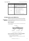
Configuring the GPIB link Power Supply setup
Configuring the GPIB link
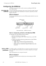
The GPIB communication link is used for remotely controlling the XMP 2600
power supply system.
Activating the
GPIB link
Activation of the GPIB communication link is done with the dip switches located at
the back of the XMP’s master mainframe but it can also be, temporarily, activated
using the front panel.
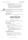
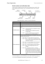
What is displayed
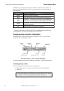
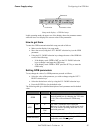
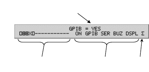
The following illustration shows the way the GPIB communication link is activated
(or disabled):
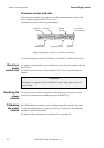
GPIB activation
selection
syste
m
symbol
syste
m
p
arameters to se
t
condense
d
modules status
Setup mode display – GPIB link activation
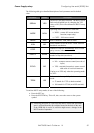
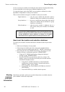
How to, temporarily, activate (or disable) the GPIB
To control the state of the GPIB link proceed as follows:
Make sure the display is in setup mode.
Move the cursor (using the LEFT / RIGHT selection keys) to the GPIB
parameter.
Using the UP / DOWN selection keys change the state of the GPIB link
to one of the following:
o “GPIB = NO” to disable the GPIB communication link.
o “GPIB = YES” to activate the GPIB communication link.
Selecting this state, automatically changes the display to the GPIB
setup mode.
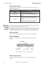
Setting GPIB
parameters
The GPIB bus address of the XMP 2600 is set using the dip switches located at the
back of the XMP’s master mainframe but it can also be, temporarily, set using the
front panel.
Other GPIB parameters are set using the front panel.
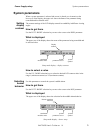
What is displayed
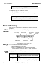
The following illustration shows the display layout when setting up the GPIB
parameters:
84 XMP 2600 User’s Guide rev. 1.0