


Rear Panel Description Installation
net
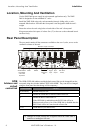
Connectors
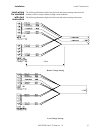
The net is a proprietary internal communication link used to connect between the
modules' controllers and the mainframe main controller. It is available at the rear
enabling linking of expansion units (containing only modules), via the main
mainframe, with the remote controller (IEEE-488 and RS-232 interface) by daisy
chaining. There are two net connectors labeled
"NET 1" and "NET 2" at the rear panel.
These connectors should be left open (unused) by the user if there are no modules
external to the mainframe.
To link expansion mainframe with external modules just connect a pin-to-pin cable
(such as TST 0330) from "NET2" in the controller to "NET1" in the expansion #1
unit. Additional units can be daisy-chained by connecting additional cables from
NET2 in the expansion #1 unit to the NET1 connector in the expansion #2 unit, etc.
Trig. In
Connector
The Trig. In connector is a BNC type connector, labeled "TRIG. IN".
It is used to trigger the modules' response to external events via hardware.
The Trig-In signal should be a TTL level signal (or open collector), able to sink
2mA to a "logic 0" level of 0.4V or less.
The modules' reaction to this signal is on the negative edge ("1" to "0" transition).
Sync. Out
Connector
The Sync. Out connector is a BNC type connector, labeled "SYNC. OUT".
It carries the Sync. Out signal, available to the user for synchronizing external
devices to the XMP 2600.
At a user selectable event, the XMP 2600 pulls the SYNC. OUT signal low for a
period of about 250-500 microseconds. This output is a standard TTL level output
with a 220 OHM series resistor. High impedance load is recommended for this
signal (Such as CMOS devices with a pull-up resistor rated 10KOHM or higher or
without a pull-up resistor).
On-Off
Connector
This connector offers the user the option of shutting down (or enabling the operation
of) the mainframe' power modules. It is a 15-pin D-TYPE female connector labeled
"ON-OFF CTRL". It, also, offers a dry contact output (both N.O. and N.C.) for
modules' operation indication.
The user can choose to control the unit by applying a 4VDC to 12VDC voltage (Rin
= 220 OHM) to inhibit (or enable) operation of the modules, or, alternatively control
the unit by applying a short to inhibit (or enable) operation of the modules.
The unit will operate normally if the male connector is not present
(ON by default).
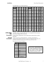
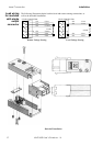
The connector (15 pin D-Type male) wiring for the four options is as follow:
option 1
Vin=0V modules operation enabled
Vin=4VDC to 12VDC modules operation inhibited
Connect as follows:
+Vin @ pin 3
-Vin @ pin 11
the +Vin and -Vin terminals are isolated and can be floated up to
±200VDC relative to the earth potential.
8 XMP 2600 User’s Guide rev. 1.0