


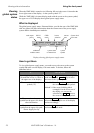


Using the front panel Viewing status information
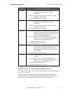
Parameter Displayed data (left to right)
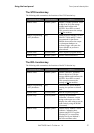
HIGH
Voltage and current thresholds for the high voltage and
current portion of the window warning
mechanism.
State of the high voltage and current window warning
mechanism: ON or OFF.
Detailed module status (see below).
LOW
Voltage and current thresholds for the low voltage and
current portion of the window warning
mechanism.
State of the low voltage and current window warning
mechanism: ON or OFF.
Detailed module status (see below).
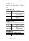
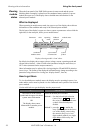
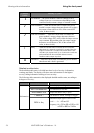
SYNC
Selection of a module condition that will cause a SYNC
signal to be generated. The SYNC signals from all
the modules are summed to produce the output at
the rear of the XMP’s mainframe.
Operating mode: VM=voltage mode (operating as a
voltage source), CM=current mode (operating as a
current source), FB=foldback is active.
Foldback selection (see below).
Detailed module status (see below).
TRIG
Selection of the module’s response to a hardware or
software trigger. Hardware trigger signal can be
fed at the rear of the XMP’s mainframe. The
signal is distributed to all the power modules in
the mainframe.
Detailed module status (see below).
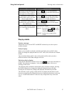
OUT
Output voltage and current as measured at the output
connector.
Operating mode: VM=voltage mode (operating as a
voltage source), CM=current mode (operating as a
current source), FB=foldback is active.
Foldback selection (see below).
Detailed module status (see below).
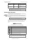
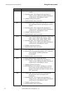
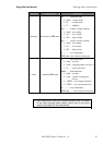
Foldback selection (current limitation scheme) indication
The behavior of the XMP’s power module when operating in current mode (current
source) is user selectable.
The following table summarizes the available selections along with the symbol
representing each one. For more details on the behavior of the power module’s
output please refer to the basic operation chapter later on in this manual.
XMP 2600 User’s Guide
rev. 1.0 33