


Basic operation Programming power module parameters
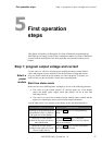
Parameter Values to program (left to right)
SET
Output voltage and current limit (or voltage limit and
output current if operating as a current source).
Current limiting scheme (Foldback selection).
RIPL
Simulated ripple at the module’s output: level (OFF, LOW
or HIGH) and frequency (50Hz, 60Hz, 100Hz,
120Hz, 400Hz, 800Hz, 2KHz).
PROT
Over voltage and over current protection threshold levels.
Protection levels programming method: AUT=automatic
(auto-tracking) or MAN=manual (user
programmed).
MAX
(none – shown for reference only)
LIM
Voltage and current values that serve as limits on the
allowed output values to program (SET parameter).
HIGH
Voltage and current thresholds for the high voltage and
current portion of the window warning mechanism.
State of the high voltage and current window warning
mechanism: ON or OFF.
LOW
Voltage and current thresholds for the low voltage and
current portion of the window warning mechanism.
State of the low voltage and current window warning
mechanism: ON or OFF.
SYNC
Selection of a module condition that will cause a SYNC
signal to be generated. The SYNC signals from all
the modules are summed to produce the output at
the rear of the XMP’s mainframe.
TRIG
Selection of the module’s response to a hardware or
software trigger. Hardware trigger signal can be fed
at the rear of the XMP’s mainframe. The signal is
distributed to all the power modules in the
mainframe.
Parameters
value limits
Voltage and current values associated with parameters (e.g. SET, PROT, HIGH)
have upper and lower limits on their allowed value.
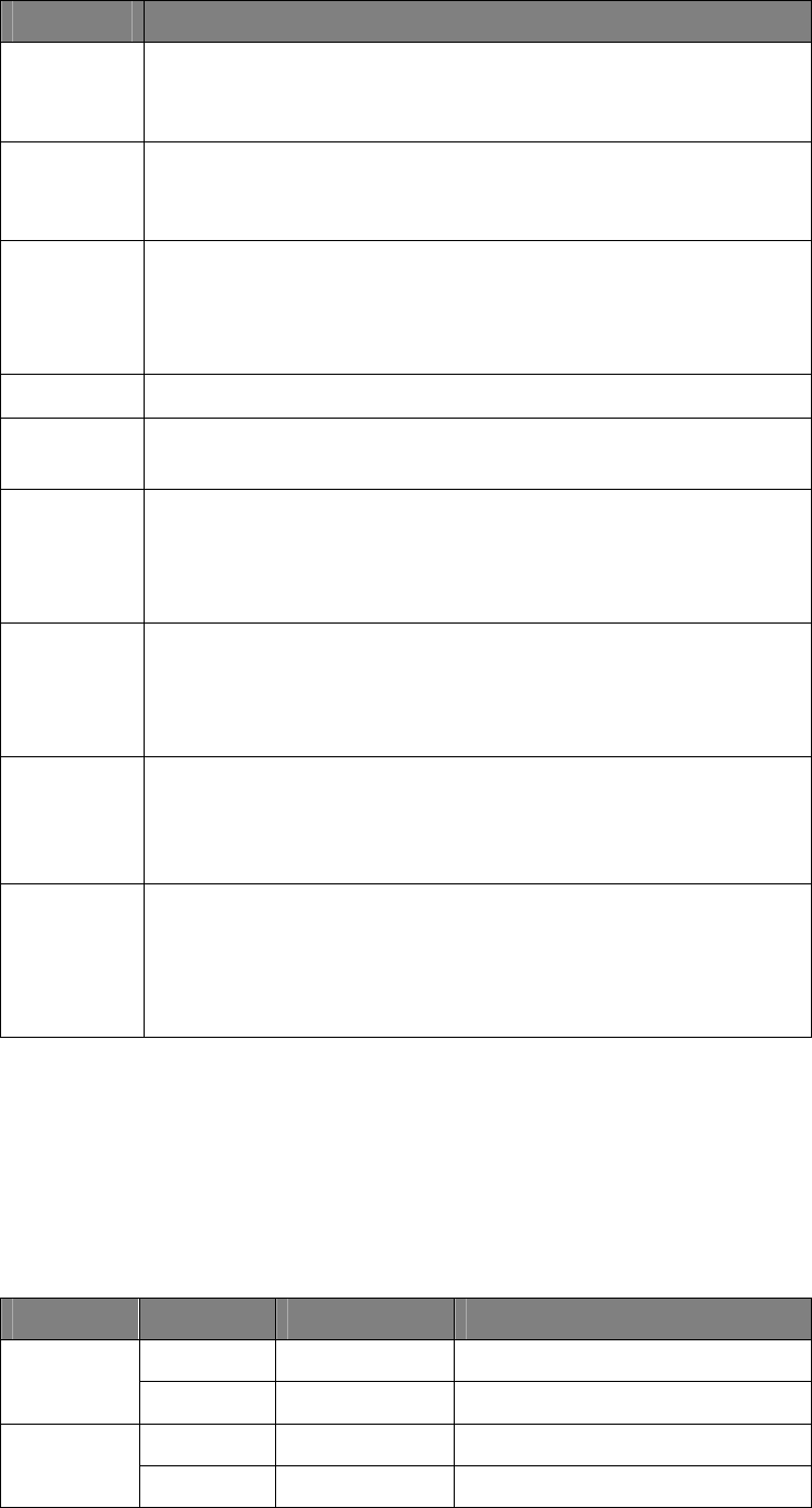
Lower and upper limits
The following table lists the upper and lower limiting values for each parameter:
Parameter Value Lower limit Upper limit
Voltage 0V The lower of: Vmax, OVset, Vlim
SET
Current Imin The lower of: Imax, OCset, Ilim
Voltage Vset Vmax + 10%
PROT
Current Iset Imax +10%
XMP 2600 User’s Guide
rev. 1.0 45