


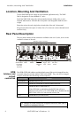
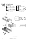
Installation Rear Panel Description
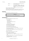
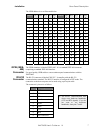
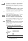
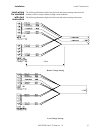
The GPIB address is set as illustrated below:
address sw 5 sw 4 sw 3 sw 2 sw 1 address sw 5 sw 4 sw 3 sw 2 sw 1
1
© 16 ©
©
2
©
17 ©
©
3
© © 18 ©
© ©
4
©
19 ©
©
5
©
© 20 ©
©
©
6
© ©
21 ©
© ©
7
© © © 22 ©
© © ©
8
©
23 © ©
9
©
© 24 © ©
©
10
©
©
25 © ©
©
11
©
© © 26 © ©
© ©
12
© ©
27 © © ©
13
© ©
© 28 © © ©
©
14
© © ©
29 © © © ©
15
© © © © 30 © © © © ©
GPIB (IEEE-
488)
Connector
The GPIB connector is labeled "IEEE-488". It is a standard IEEE-488 connector,
comprising a standard IEEE-488 interface.
Use good quality GPIB cables to ensure uninterrupted communications with the
XMP 2600.
RS-232
Connector
The RS-232 connector is labeled "RS-232". It complies with the RS-232
communications standard. The RS-232 interface is configured in DTE mode. The
connection to the host computer can be made using a pin-to-pin cable.
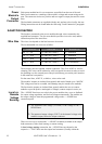
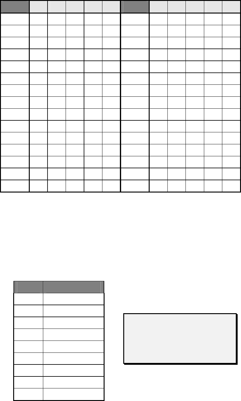
The connector’s pin out is as follows:
Pin # Signal
1 DTR
2 TX
3 RX
4 Not Connected
5 GND
6 DTR
7 CTS
8 RTS
9 Not Connected
The RS232 communication link
always uses hardware handshake
(CTS and RTS signals). If you do
not want to use hardware
handshake, short pins 7 and 8.
XMP 2600 User’s Guide
rev. 1.0 7