


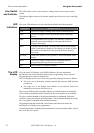
Using the front panel Viewing status information
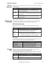
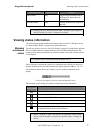
Operating mode Cursor location Function
Status mode Any Toggle the global enable state of
the outputs (as depicted by the
ON indicator)
All other modes Any Globally disable all the outputs (if
enabled)
Keeping any key pressed for more than a second invokes repeat of
the key function, at a rate of 10 times in a second.
Viewing status information
The following paragraphs detail the information shown on the LCD display in the
two status display modes: system status and module status.
Modules
condensed
status
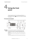
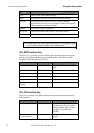
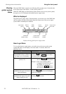
The left part of the lower row of the LCD display contains 16 symbols that represent
the 16 available channels (module addresses) of the XMP 2600 mainframe. The
captions on the front panel indicate the channel number associated with the symbol
on the display.
Channels 10 to 16 are marked with the letters A to G.
Each of the above mentioned symbols is a condensed status display for the power
module installed in the associated channel (having the indicated address: 1 to 16).
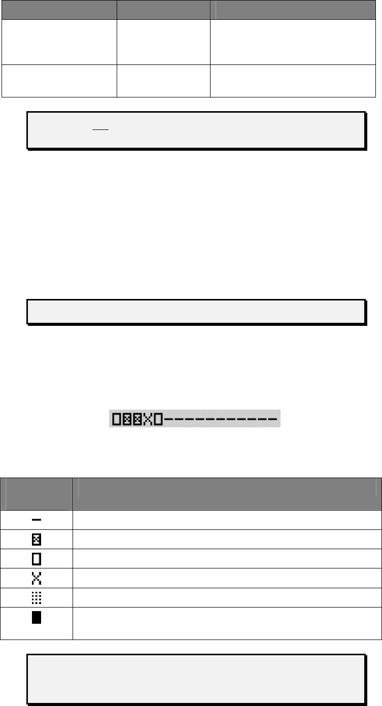
The illustration below shows an example of power modules condensed status
display.
Portion of the display showing condensed modules status
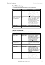
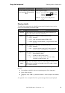
The meaning of each displayed symbol is summarized in the table below.
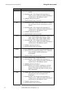
Condensed
status symbol
Meaning of symbol
Channel is free – no power module is installed with that address.
Power module is OK with its output turned off.
Power module is OK with its output turned on.
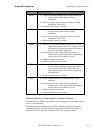
Power module is OK with its output disconnect relay open.
Power module has a fault (e.g. OVP, OCP etc.).
Power module is malfunctioning (e.g. it does not respond to
communications from the main controller).
When a warning or fault event occurs, the condensed status symbol
blinks until the module is selected for detailed status viewing (see
below).
XMP 2600 User’s Guide
rev. 1.0 27