


Location, Mounting And Ventilation Installation
Location, Mounting And Ventilation
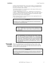
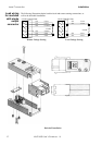
Use the XMP 2600 power supply in rack-mounted applications only. The XMP
2600 is designed to fit into standard 19” racks.
Install the XMP 2600 using only rack-mounted telescopic sliding rails, or rack-
mounted slide brackets. Note that the front panel is not designed to hold the unit’s
weight.
Fasten the unit to the rack using bolts on both sides of the unit’s front panel.
Keep an unrestricted air space of at least 5cm (2”) at the rear so the exhausted hot air
can flow freely.
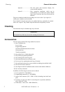
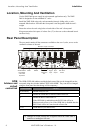
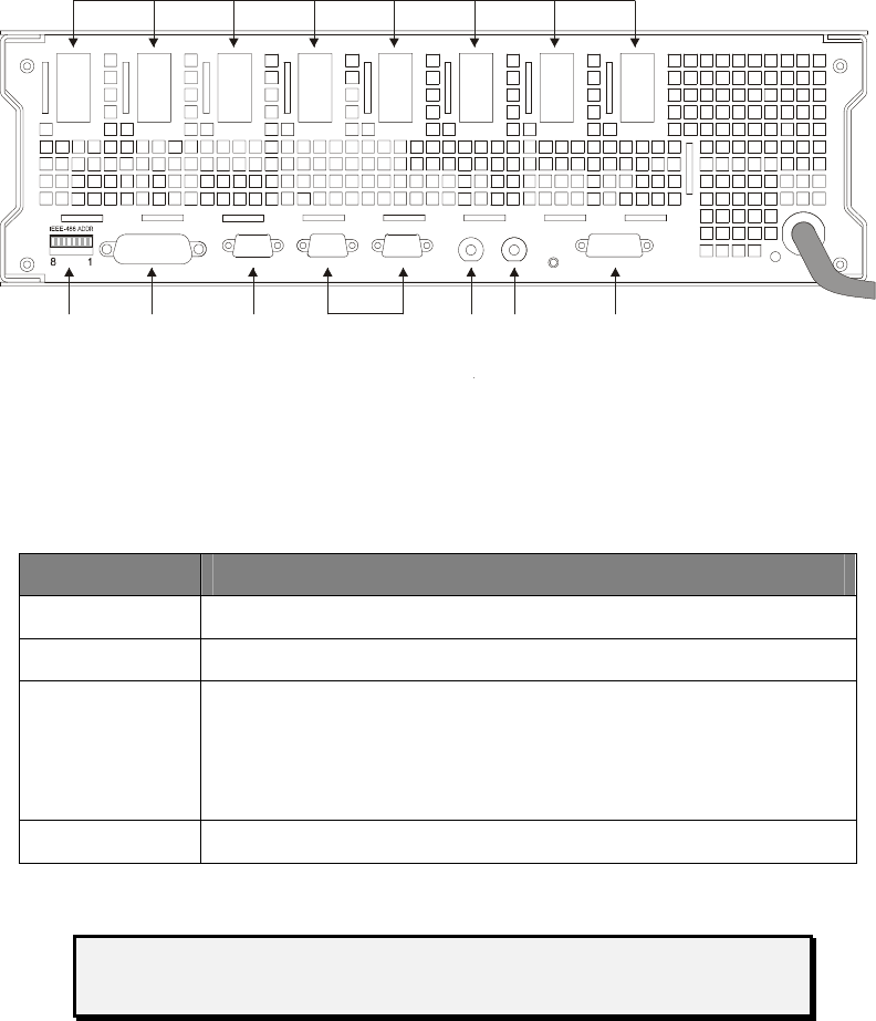
Rear Panel Description
The rear panel contains all the connectors available to the user. It, also, serves as the
ventilation exhaust of the unit.
IEEE-488 RS-232 NET 2
NET 1
TRIG IN SYNC OUT ON-OFF CTRL
S8 S7 S6 S5 S4 S3 S2 S1
Module’s output connectors
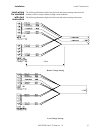
Net
expansion
link
GPIB address
and default
control link
di
p
-switc
h
GPIB
RS232
Trigger
input
Sync
output
ON / OFF
control
. . . . .
GPIB
Address and
default
control link
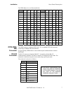
The GPIB (IEEE-488) address and the default control link can be changed from the
rear panel using the switches labeled "IEEE-488 ADDR". They can also be changed
using the front panel but that change will be temporary.
Switch number function
8 (left most) Should always be UP.
7 Enable the GPIB link for remote control when UP.
6 Enable the RS232 link when UP.
If the GPIB link is enabled then the RS232 link will be in
Monitor mode at Power On. If the GPIB link is disabled then the
RS232 link will be in Control mode at Power On.
5 to 1 GPIB address (see table below).
Changes in switch position are recognized when the XMP 2600 is
turned on or undergoes full reset.
6 XMP 2600 User’s Guide rev. 1.0