


Power Supply setup Power module setup
Serial number and calibration date
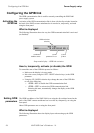
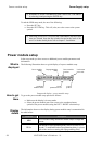
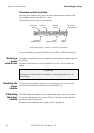
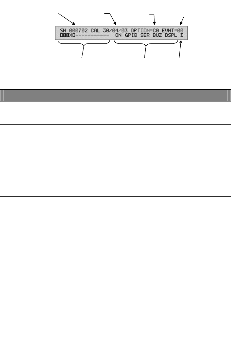
Select the power module (move the cursor to the condensed status symbol of the
power module) and press the RCL key. The illustration, below, shows a typical
display.
Last value of
event status b
y
te
syste
m
symbol
syste
m
p
arameters to se
t
condense
d
modules status
Module’s
serial number
Calibratio
n
date
Installe
d
o
p
tions
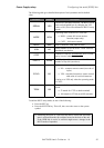
Setup mode display – module’s controller information
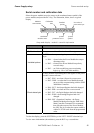
Information shown Description
Serial number
Power module serial number.
Calibration date
Last power module calibration date: dd/mm/yy.
Installed options
A HEX number representing the power module options
byte:
Bit 4.... cleared when the Power Module has output
disconnect relay.
Bit 5.... cleared if the Power Module has polarity
reversal relays.
Bit 3.... set if this module has power monitoring
logic (e.g. 1/8
wide
36V/40A module)
Event status byte
A HEX number representing the event register of the power
module’s status structure:
Bit 7: PON : set when a Power On event occurs.
Bit 5: CMD : set when the Power Module detected
an error while communicating with the XMP
2600 Main Controller..
Bit 4: OUT : the Output Register had a bit changed.
Bit 3: ERR : set when an Error event occurred.
Bit 2: FLT : the Faults Register had a bit changed.
Bit 1: WRN : the Warnings Register had a bit
changed.
Bit 0: OPC : Operation Complete - the Power
Module finished processing the XMP 2600
Main Controller Command. For commands
that effect the output of the Power Module,
the OPC flag is set when the output settled to
within 2% of full scale from the programmed
value.
To clear the display, press the SYSTEM key or the LEFT / RIGHT selection keys.
To view more information (shown below) press the RCL key a second time.
XMP 2600 User’s Guide
rev. 1.0 89