


158 www.xilinx.com Ethernet AVB Endpoint User Guide
UG492 July 23, 2010
Chapter 15: Detailed Example Design (Standard Format)
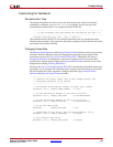
Viewing the Simulation Wave Form
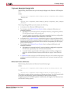
The Simulation Scripts for the selected simulator automatically selects signals of interest
from within the DUT and adds them to the simulator wave window. These are organized
into grouped interfaces, which are identified using section headings in the wave window.
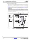
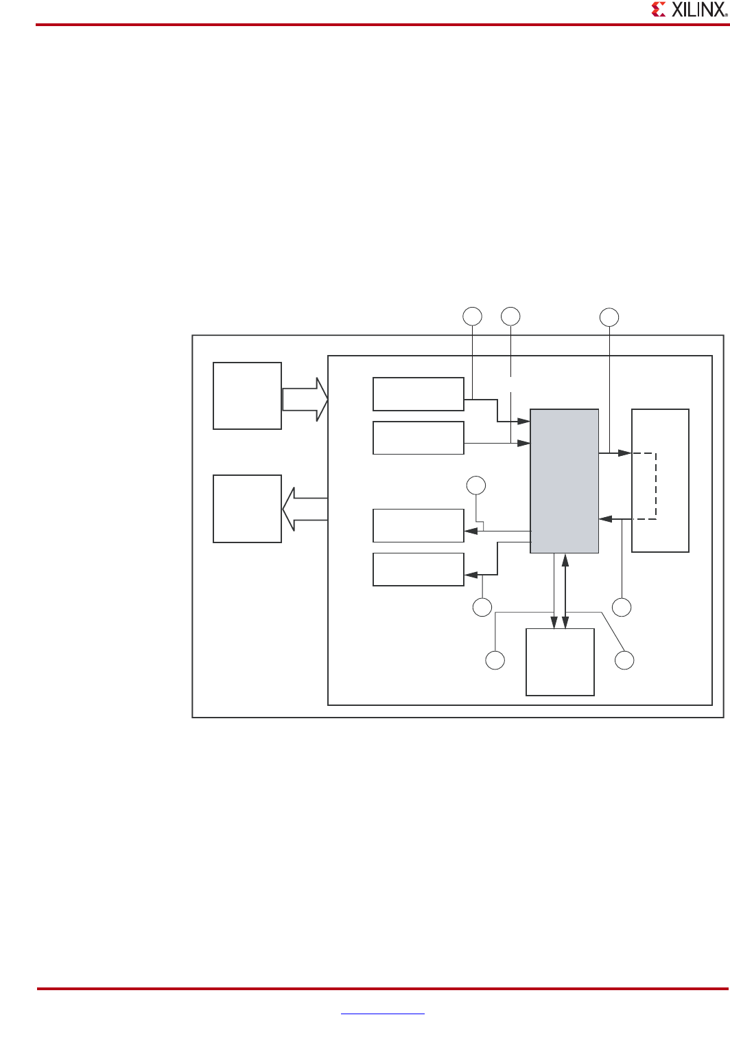
Figure 15-3 illustrates the grouped interfaces selected for the Functional Simulation. The
circled numbers represent the order in which they are displayed (the wave window section
headings are also numbered to match Figure 15-3). Further signals of interest may be
added as desired.
The signals added to the Timing Simulation are a subset of the ones used in the Functional
Simulation. To summarize, the PLB interface is not viewed, due to
synthesis/implementation optimization that occurs on these signals, the result of which
merges signals and changes names.
X-Ref Target - Figure 15-3C
Figure 15-3: Simulator Wave Window Contents
Legacy
Traffic
PLBInterrupts
AV T raffic
Legacy
Traffic
1
4
2
3
AV Traffic
5
7 8
6
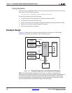
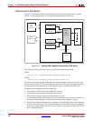
Demonstration Test Bench
PLB
Module
Tx Frame
Stimulus
Tx Frame
Stimulus
Rx Frame
Checker
Rx Frame
Checker
Ethernet
AVB
Endpoint
Core
Loopback
Module
Clock
and
Reset
Generation
Statistic
Gathering
Example Design Top Level