


94 www.xilinx.com Ethernet AVB Endpoint User Guide
UG492 July 23, 2010
Chapter 10: Configuration and Status
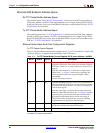
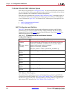
Tx Arbiter Send Slope Control Register
The sendSlope variable is defined in IEEE P802.1 Qav to be the rate of change of credit, in
bits per second, when the value of credit is decreasing (during AV packet transmission).
Together with the “Tx Arbiter Idle Slope Control Register,” registers define the maximum
limit of the bandwidth that is reserved for AV traffic; this will be enforced by the
“Tx
Arbiter.”
The default values allow the maximum bandwidth proportion of 75% for the AV
traffic. See the IEEE P802.1 Qav specification and “Tx Arbiter” for more information.
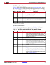
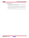
Tx Arbiter Idle Slope Control Register
The idleSlope variable is defined in IEEE802.1Qav to be the rate of change of credit, in bits
per second, when the value of credit is increasing (whenever there is no AV packet
transmission). Together with the “Tx Arbiter Send Slope Control Register,” two registers
define the maximum limit of the bandwidth that is reserved for AV traffic; this is enforced
by the
“Tx Arbiter.” The default values allow the maximum bandwidth proportion of 75%
for the AV traffic. See the IEEE P802.1 Qav specification and “Tx Arbiter” for more
information.
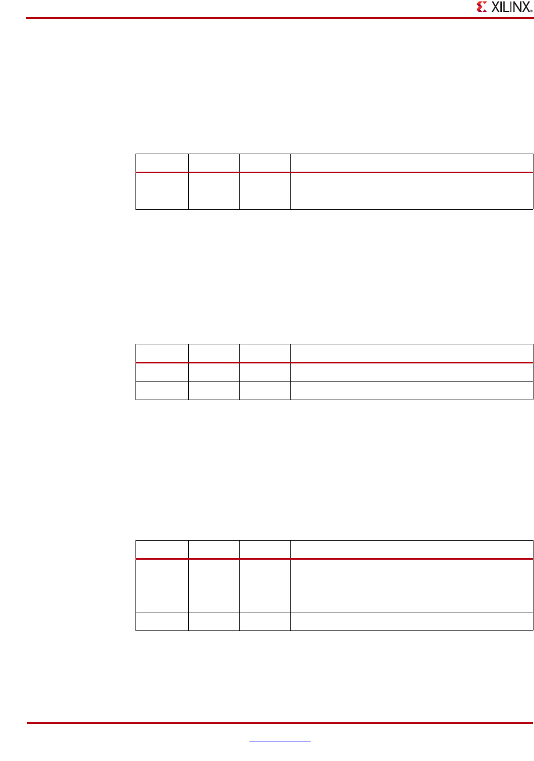
RTC Offset Control Registers
Table 10-6 describes the offset control register for the nanoseconds field of the “Real Time
Clock,” used to force step changes into the counter. When in PTP clock master mode, this
can be used to set the initial value following power-up. When in PTP clock slave mode, the
“Software Drivers” will use this register to implement the periodic step corrections.
This register and the registers defined in Table 10-7 and in Table 10-8 are linked. These
three offset values will be loaded into the RTC counter logic simultaneously following a
write to this nanosecond offset register.
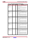
Table 10-7 describes the offset control register for the lower 32-bits of seconds field of the
“Real Time Clock,” used to force step changes into the counter. When in PTP clock master
mode, this can be used to set the initial value following power-up. When in PTP clock slave
mode, the “Software Drivers” use this register to implement the periodic step corrections.
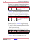
Table 10-4: Tx Arbiter Send Slope Control Register (PLB_base_address + 0x200C)
Bit no Default Access Description
19-0 2048 R/W The value of “sendSlope”
31-20 0 RO Unused
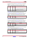
Table 10-5: Tx Arbiter Idle Slope Control Register (PLB_base_address + 0x2010)
Bit no Default Access Description
31-20 0 RO Unused
19-0 6144 R/W The value of “idleSlope”
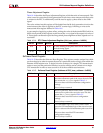
Table 10-6: RTC Nanoseconds Field Offset (PLB_base_address + 0x2800)
Bit no Default Access Description
29-0 0 R/W 30-bit offset value for the RTC nanoseconds field. Used
by the microprocessor to initialize the RTC, then
afterwards to perform the regular RTC corrections
(when in slave mode).
31-30 0 RO Unused