


78 www.xilinx.com Ethernet AVB Endpoint User Guide
UG492 July 23, 2010
Chapter 8: Real Time Clock and Time Stamping
There are two stages to the implementation:
(Step 1) Controlled Frequency RTC
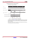
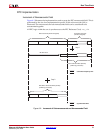
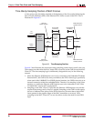
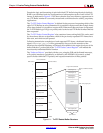
The RTC Increment Value illustrated in Figure 8-2 is set directly from the “RTC Increment
Value Control Register.” The upper 6 bits of this register align with the lower 6 bits of the
RTC nanoseconds field. The lower 20-bits of the RTC Increment Value align with the 20-bit
sub-nanoseconds field. It is assumed that the frequency of the RTC reference clock is
known by the processor to enable the increment value to be programmed correctly. For
example, if the RTC is being clocked from a 125 MHz clock source, a nominal increment
value of 8 ns should be programmed (by writing the value 0x800000 into the “RTC
Increment Value Control Register”). However, if the microprocessor determines that this
clock is drifting with respect to the grand master clock, it can revise this nominal 8 ns up or
down by a very fine degree of accuracy.
The “step 1” addition illustrated in Figure 8-2 (of current counter value plus increment)
will occur on every clock cycle of the RTC reference clock. The result from this addition
forms the new value of the “controlled frequency RTC” nanoseconds field. This controlled
frequency RTC will initialize to zero, following reset, and will continue to increment
smoothly on every RTC reference clock cycle by the current value contained in the RTC
Increment Value Control Register.
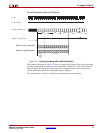
Figure 8-2 illustrates that 26 bits have been reserved for the Increment Value, the upper 6-
bits of which overlap into the nanoseconds field. For this reason, the largest per-cycle
increment = 1ns * 2^6 = 64 ns. The lowest clock period which is expected to increment this
counter is 40 ns (corresponding to the 25 MHz MAC clock used at 100 Mbps speeds). So
this should satisfy all allowable clock periods.
(Step 2) Synchronized RTC
The value contained in the “RTC Offset Control Registers” written by the microprocessor,
is then applied to the free running “controlled frequency RTC” counter. This is used by the
microprocessor to:
• Initialize the power-up value of the Synchronized RTC.
• Apply step corrections to the Synchronized RTC (when a slave), based on the timing
PTP packets received from the Grand Master Clock RTC.
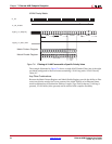
The “step 2” addition illustrated in Figure 8-2 (of controlled frequency RTC value plus
offset) will occur on every clock cycle of the RTC reference clock. The result from this
addition forms the new value of the Synchronized RTC nanoseconds field. It is this version
of the RTC nanoseconds field which is made available as an output of the core - the
rtc_nanosec_field[31:0] port.
Increment of the Seconds Field
The RTC seconds field is, conceptually, implemented in a similar way to the nanoseconds
field. The seconds field should be incremented by a value of one whenever the
synchronized RTC nanoseconds field saturates at one-second. The “RTC Offset Control
Registers” allow the software to make large step corrections to the seconds field in a
similar manner. Again, the step correction capability can be used to either initialize the
RTC counter following reset, or to synchronize the local RTC to that of the Grand Master
Clock (when the local device is acting as a clock slave).