


Ethernet AVB Endpoint User Guide www.xilinx.com 83
UG492 July 23, 2010
Chapter 9
Precise Timing Protocol Packet Buffers
This chapter considers two of the logical components which are partly responsible for the
AVB timing synchronization protocol.
• “Tx PTP Packet Buffer”
• “Rx PTP Packet Buffer”
These are both described in this chapter as they are closely related.
Tx PTP Packet Buffer
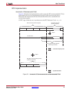
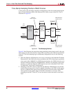
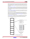
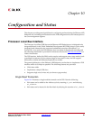
The Tx PTP packet buffer is illustrated in Figure 9-1. This packet buffer provides working
memory to hold the PTP frames which are required for transmission. The software drivers,
via the PLB configuration bus, can read/modify/write the PTP frame contents, and
whenever required, can request transmission of the appropriate PTP frames.
The PTP packet buffer is implemented in dual-port block RAM. Port A of the block RAM is
connected to the PLB configuration bus: all addresses in the buffer are read/writable
through the PLB. Port B of the block RAM is connected to the Tx Arbiter module, allowing
PTP frames to be read out of the block RAM and transmitted through the connected
TEMAC.
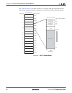
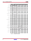
The Tx PTP Packet Buffer is divided into eight identical buffer sections as illustrated. Each
section contains 256 bytes, which are formatted as follows:
• the first byte, at address zero, contains a frame length field. This indicates how many
bytes make up the PTP frame that is to be transmitted from this particular PTP buffer.
• The next seven bytes, from address 1 to 7, are reserved for future use.
• The PTP frame data itself is stored from address 8 onwards. The amount of addresses
used is dependent on the indicated frame length field, which will be different for each
PTP frame type. Each PTP buffer provides a maximum of 244 bytes (more than that
required for the largest PTP frame). Each PTP frame holds the entire MAC frame
(with the exception of any required MAC padding or CRC - these will automatically
be inserted by the TEMAC) from the Destination Address field onwards.
• The top four addresses of each buffer, from address 0xFC to 0xFF are reserved for a
time stamp field. At the beginning of PTP frame transmission from any of the eight
buffers, the “Time Stamping Logic” will sample the “Real Time Clock”. Following the
end of PTP frame transmission, this captured timestamp will automatically be written
into this location to accompany the frame for which it was taken.