


Ethernet AVB Endpoint User Guide www.xilinx.com 79
UG492 July 23, 2010
Time Stamping Logic
Clock Outputs Based on the Synchronized RTC Nanoseconds Field
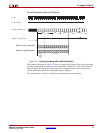
The clk8k (8 kHz clock) output, derived from the Synchronized RTC, is provided as an
output from the core. The synchronized RTC counter, unlike the controlled frequency
version, has no long-term drift (assuming the provided software drivers are used
correctly). Therefore, the clk8k signal will be synchronized exactly to the network RTC
frequency.
The 8 kHz clock is the period of the shortest class measurement interval for an SR class as
specified in IEEE802.1Qav. This clock could also be useful for external applications (for
example, a 1722 implementation of the AV traffic).
Time Stamping Logic
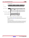
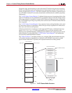
Whenever a PTP packet, used with the Precise Timing Protocol (PTP), is transmitted or
received (see “Precise Timing Protocol Packet Buffers” in Chapter 9), a sample of the
current value of the RTC is taken and made available for the software drivers to read. The
hardware makes no distinction between frames carrying event or general PTP messages
(as defined in IEEE P802.1AS); it will always store a timestamp value for ethernet frames
containing the Ethertype specified for PTP messages.
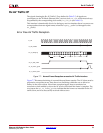
This time stamping of packets is a key element of the tight timing synchronization across
the AVB network wide RTC, and these samples must be performed in hardware for
accuracy. The hardware in this core will therefore sample and capture the local
nanoseconds RTC field for every PTP frame transmitted or received. These captured time
stamps are stored in the “Precise Timing Protocol Packet Buffers” alongside the relevant
PTP frame, and are read and used by the PTP software drivers.
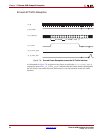
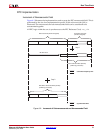
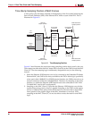
It is important to realize that is it actually the “controlled frequency RTC” nanoseconds
field which is sampled by the time stamping logic rather than the synchronized RTC (see
Figure 8-2). This is important when operating as a clock slave: the controlled frequency
RTC always acts as a smooth counter whereas the synchronized RTC may suffer from
occasional step changes (whenever a new offset adjustment is periodically applied by the
software drivers). These step changes, avoided by using the controlled frequency RTC,
could otherwise lead to errors in the various PTP calculations which are performed by the
software drivers.
Note:
The “Software Drivers” can themselves obtain (when required) the local synchronized RTC
value simply by summing the captured time stamp with the current nanoseconds offset value of the
“RTC Offset Control Registers” (effectively performing the step 2 calculation of Figure 8-2 in
software).