Ethernet AVB Endpoint User Guide www.xilinx.com 97
UG492 July 23, 2010
PLB Address Map and Register Definitions
Phase Adjustment Register
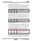
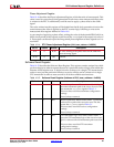
Table 10-14 describes the Phase Adjustment Register, which has units of nanoseconds. This
value is used to correct the 8k clock generation circuit when a new nanosecond offset value
is written to the RTC. It additionally could be used to apply a phase offset to the clk8k
signal.
The value written into this register will be loaded into the 8k clock generation circuit at the
same instant as the offset is applied to the RTC counter logic, following a write to the
nanosecond offset register defined in Table 10-6.
As an example of applying a phase offset, writing the value of the decimal 62500 (half of an
8 KHz clock period) to this register would invert the
clk8k signal with respect to a value of
0. This register can therefore provide fine grained phase alignment of these signals to a 1 ns
resolution.
Software Reset Register
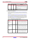
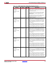
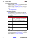
Table 10-15 describes the Software Reset Register. This register contains unique bits which
can be written to in order to request the reset of a particular section of logic from within the
Ethernet AVB Endpoint core. A single bit can be written to in a single CPU transaction in
order to reset just that particular function; several to all bits can be written to in a single
CPU transaction in order to reset several to all of the available reset functions.
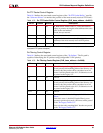
Table 10-14: RTC Phase Adjustment Register (
PLB_base_address + 0x2824)
Bit no Default Access Description
29-0 0 R/W ns value relating to the phase offset for the clk8k RTC
derived timing signal.
31-30 0 RO Unused
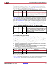
Table 10-15: Software Reset Register (Address at PLB_base_address + 0x2828)
Bit Number Default Access Description
0 0 WO Transmitter path reset. When written with a '1', forces
the entire transmitter path of the core to be reset. This
also asserts the tx_reset signal of Table 5-1.
This reset does not affect transmitter configuration
settings.
If read, always returns 0.
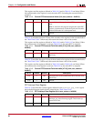
1 0 WO Receiver path reset. When written with a '1', forces the
entire receiver path of the core to be reset. This also
asserts the rx_reset signal of Table 5-1.
This reset does not affect receiver configuration
settings.
If read, always returns 0.
2 0 WO PTP Transmitter logic reset. When written with a '1',
forces the PTP transmitter logic of the core to be reset.
This is a subset of the full transmitter path reset of bit
0.
This reset does not affect PTP transmitter
configuration settings.
If read, always returns 0.


