


Ethernet AVB Endpoint User Guide www.xilinx.com 47
UG492 July 23, 2010
Core Interfaces
Core Interfaces
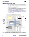
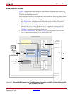
All ports of the core are internal connections in FPGA fabric.
All clock signals are inputs and no clock resources are used by the core. This enables clock
circuitry to be implemented externally to the core netlist, providing full flexibility for clock
sharing with other custom logic.
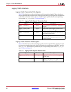
Clocks and Reset
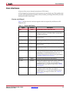
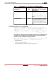
Table 5-1 defines the clock and reset signals which are required by the Ethernet AVB
Endpoint core.
Table 5-1: Clocks and Resets
Signal Direction Description
reset Input Asynchronous reset for the entire core
rtc_clk Input Reference clock used to increment the “RTC.” The
minimum frequency is 25 MHz. Xilinx recommends a
125 MHz clock source.
tx_clk Input The MAC transmitter clock, provided by the Tri-Mode
Ethernet MAC.
tx_clk_en Input A clock enable signal: this must be used as a qualifier
for tx_clk.
rx_clk Input The MAC receiver clock, provided by the Tri-Mode
Ethernet MAC.
rx_clk_en Input A clock enable signal: this must be used as a qualifier
for rx_clk.
host_clk Input An input clock for the management interface of the
connected Tri-Mode Ethernet MAC. This clock can be
independent, or could be shared with PLB_clk.
This signal is only present when the core is generated in
“Standard CORE Generator Format”.
PLB_clk Input The input clock reference for the PLB bus.
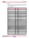
tx_reset Output Output reset signal for logic on the Legacy Traffic and
AV Traffic transmitter paths. This reset signal is
synchronous to tx_clk; the reset is asserted when a
transmitter path reset request is made to the “Software
Reset Register.”
rx_reset Output Output reset signal for logic on the Legacy Traffic and
AV Traffic receiver paths. This reset signal is
synchronous to rx_clk; the reset is asserted when a
receiver path reset request is made to the “Software
Reset Register.”