


TRACER 6000 Series Integrated System Manual Section 2 Microwave Path Engineering Basics
612806420L1-1F Copyright © 2005 ADTRAN, Inc. 17
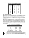
where the variables in the equations are defined as
P
R
received power (dBm)
P
sens
receiver sensitivity (dBm)
P
T
transmitted power (adjustable up to 20, 24, or 27 dBm maximum – depending on product)
G
T
transmit antenna gain (decibels referenced to an isotropic source – dBi)
G
R
receive antenna gain (dBi)
L other losses (RF coaxial cable, etc. – dB)
L
P
path loss (dB)
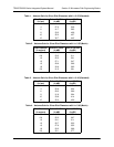
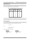
Higher levels of fade margin indicate stronger protection against signal fading and a more reliable link. For
most applications, 20 to 30 dB of fade margin should ensure a reliable link. ADTRAN provides a free
wireless link planner tool on the ADTRAN website (www.adtran.com
– see Service/Support > Technical
Support > TRACER Products).
The following sections further discuss the necessary power calculations and their components.
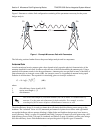
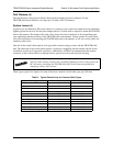
4. RECEIVER POWER
The viability of a particular microwave path is determined by the power of the transmitted microwave
signal, the transmit and receive antenna gain, distance, and accumulated system losses (such as RF coaxial
cable losses and path loss).
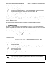
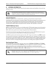
The equation relating received signal power to the other microwave parameters is
or (in decibel notation)
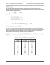
where the variables in the equations are defined as
P
R
received power (dBm)
P
T
transmitted power (adjustable up to 20, 24, or 27 dBm maximum – depending on product)
G
T
transmit antenna gain (decibels referenced to an isotropic source – dBi)
G
R
receive antenna gain (dBi)
λ carrier wavelength (meters)
d path distance (meters)
L other losses (RF coaxial cable, etc. – dB)
L
P
path loss (dB)
When using decibel notation, all quantities must be individually converted to decibels
prior to performing addition and subtraction.
P
R
P
T
G
T
G
R
λ
2
4
π
()
2
d
2
L
------------------------------=
(watts, W)
(decibels referenced to a milliwatt, dBm)
P
R
= P
T
+ G
T
+ G
R
- L - L
P