


Section 5 User Interface Guide TRACER 6000 Series Integrated System Manual
58 Copyright © 2005 ADTRAN, Inc. 612806420L1-1F
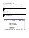
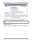
C. RF Status
A graphical indicator of the RF links is located beneath the Elapsed Time display. The status of the
received radio link is indicated as
RF UP or RF DOWN for each direction. This RF status display
corresponds to the
RF DWN LED on the front of the unit.
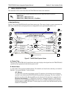
D. Remote System Status
The right portion of the TRACER 64x0 System Status menu page reports the status of the remote
TRACER 64x0 (the system across the wireless link from the active terminal). If the RF link is down in
either direction,
DATA NOT AVAILABLE is displayed in place of the remote system status information.
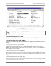
E. Local System Status
The left portion of the TRACER 64x0 System Status menu page reports the status of the local
TRACER 64x0 (the system where the active terminal is attached).
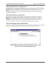
F. System Alarm Status
Indicates whether there are active system alarms (temperature, fan, or link) for the TRACER 64x0
unit. During alarm conditions,
SYSTEM ALARM is displayed in reverse highlighted text. More details on
the current system alarm is found on the
SYSTEM ALARMS page.
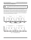
G. Frequency Plan
Displays the frequency plan (A or B) for the TRACER 64x0 unit. For an operational TRACER 64x0
system, you should have one A and one B frequency plan.
H. Rx Quality
Displays an indicator of receive signal quality that is not necessarily related to receive signal level (for
both the local and remote units) using a series of symbols (
#) and a numeric value. The more symbols
(
#) displayed, the better the signal quality. This indicator is related to signal-to-noise ratio and features
a colon (:) marker to indicate 10
-6
bit error rate. This indicator is useful as a diagnostic tool to help
identify interference, as the system may have high receive signal level and poor signal quality in
situations where interference is an issue.
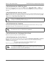
QUAD ETHERNET SWITCH MODULE
A visual status of current errors/alarms on the Ethernet interfaces (for both the local and
remote systems) is provided on the TRACER 6420 System Status menu page. The
configured data rate (on the Datapath Provisioning page) is displayed. Individual status
notations for the available Ethernet interfaces are available through the Quad Ethernet
Switch Module Status page.
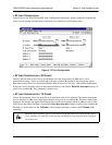
4XE1 MODULES
A visual status of current errors/alarms on the E1 interfaces (for both the local and remote
systems) is provided on the System Status menu page. The four available E1 interfaces on
the module (
A through D) are only displayed if the interface is mapped in the DATAPATH
P
ROVISIONING; a – is displayed for inactive, unmapped interfaces. The interface displayed in
reverse highlight indicates an active error or alarm condition on the specified interface (
A
through
D). Individual E1 status pages (accessible from the Main menu) provide detailed E1
information.