


TRACER 6000 Series Integrated System Manual Section 5 User Interface Guide
612806420L1-1F Copyright © 2005 ADTRAN, Inc. 63
> RF LINK CONFIGURATION
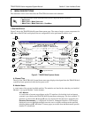
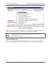
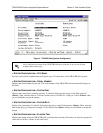
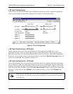
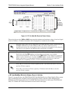
Figure 5 shows the TRACER 64x0 RF Link Configuration menu page, which contains the transmit and
receive power settings and band plan configuration for both the local and remote units.
Figure 5. RF Link Configuration
> RF LINK CONFIGURATION > RX POWER
Displays the real-time receiver levels (for both the local and remote units) in dBm and a visual
approximation using a series of symbols (
#). The more symbols (#) displayed, the stronger the signal.
Real-time receiver levels are displayed within ±5 dBm accuracy and can vary with extreme temperatures.
If the link is down in either direction and remote end data is unavailable,
DATA NOT AVAILABLE displays in
place of the symbols (
#). This parameter is display only.
> RF LINK CONFIGURATION > TX POWER
Allows the transmitter levels (for both the local and remote units) to be adjusted. The current transmitter
level is displayed in dBm or a visual approximation using a series of symbols (
#). The more symbols (#)
displayed, the stronger the signal. Real-time receiver levels are displayed within ±1 dBm accuracy. If the
link is down and remote end data is unavailable,
DATA NOT AVAILABLE displays in place of the symbols (#).
Pressing (+) on this field sets the
TX POWER to full strength; pressing (-) reduces the TX POWER to the
minimum.
Reducing the transmitter power of the remote TRACER 64x0 could cause the RF link to
drop, requiring a technician to increase the transmit power by using the menu system at
the remote site.