


TRACER 6000 Series Integrated System Manual Section 5 User Interface Guide
612806420L1-1F Copyright © 2005 ADTRAN, Inc. 57
3. MENU DESCRIPTIONS
The remainder of this section describes the TRACER 64x0 menus and submenus.
> SYSTEM STATUS
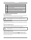
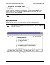
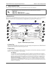
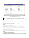
Figure 2 shows the TRACER 64x0 System Status menu page. The status of major system components for
both sides of the RF link are displayed, but no configuration can be performed from this view.
Figure 2. TRACER 64x0 System Status
A. Elapsed Time
The top of the TRACER 64x0 System Status menu page displays the elapsed time the TRACER 64x0
system has been operational since the last power reset.
B. Module Status
A visual status of the current installed modules. The modules are listed in the order they are installed
(Module 1 on top and Module 2 on the bottom).
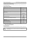
The menu structure of the TRACER 64x0 system is depicted below as follows:
> MENU PAGE
> MENU PAGE > MENU SELECTION
> MENU PAGE > MENU SELECTION > SUB-MENU
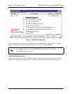
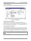
4XT1 MODULE
A visual status of current errors/alarms on the T1 interfaces (for both the local and remote
systems) is provided on the TRACER 6420 System Status menu page. The four available T1
interfaces on the module (
A through D) are only displayed if the interface is mapped in the
DATAPATH PROVISIONING; a – is displayed for inactive, unmapped interfaces. The interface
displayed in reverse highlight indicates an active error or alarm condition on the specified
interface (
A through D). Individual T1 status pages (accessible from the Main menu) provide
detailed T1 information.
A
Elapsed
Time
E
G
C
RF Status
D
Remote
G
I
Rx Power
J
Tx Power
J
Tx Power
K
Navigation Reminders
TRACER
Plan
Frequency
Plan
Status
H
Module Status
B
Local
Frequency
I
Rx Power
Module Status
Status
TRACER
Rx Quality
Rx Quality
B
L
Real-Time
Signal Values
F
Alarm Status
F
Alarm Status
H