


Section 3 Engineering Guidelines TRACER 6000 Series Integrated System Manual
34 Copyright © 2005 ADTRAN, Inc. 612806420L1-1F
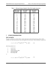
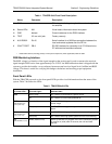
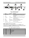
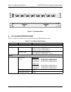
Figure 3. TRACER 64x0 Rear Panel
MGMT 10/100BaseT/TX Connection (RJ-48C)
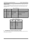
The physical Ethernet interface is provided by a single RJ-48C jack (labeled MGMT) that delivers
10/100BaseT/TX for LAN connectivity. The
MGMT port is used for Telnet, SNMP, and TFTP access and
is not a router interface. The
MGMT port has a green LINK LED to indicate a valid link and an amber ACT
LED that flashes with data activity on the interface. Table 7 shows the pinout.
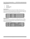
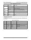
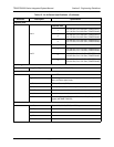
Table 6. Rear Panel Description
1
1 Detailed discussions (including pinouts) of rear panel components (where applicable) follow the table.
Name Connector Description
A Network Module
Slots
N/A Dual network module slots for system flexibility (shown
with a single 4xT1 module and a Quad Ethernet Switch
module installed)
B
MGMT RJ-45
10/100BaseT/TX Ethernet interface for SNMP, TFTP, and
Telnet access
C DC Power Terminal block 21 to 60 VDC power source connection (either polarity
referenced to ground)
D Fuse N/A 2A, 250 V, 2-inch slo-blo fuse
E Alarm Terminal block External alarm monitoring system connection
F Antenna N-type (female) Antenna feedline cable connection
G Ground Lug N/A Earth ground connection
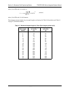
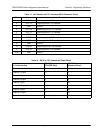
Table 7. MGMT 10/100BaseT/TX Interface Pinout
Pin Name Description
1
TX1 Transmit positive
2 TX2 Transmit negative
3 RX1 Receive positive
4,5 — Unused
6 RX2 Receive negative
7, 8 — Unused
Antenna
DC Power
Connection
Connector
Ground
Lug
Fuse
Alarm
Contacts
C
F
B
E
D
G
Ethernet
Interface
Network
Module Slots
A