


TRACER 6000 Series Integrated System Manual Section 3 Engineering Guidelines
612806420L1-1F Copyright © 2005 ADTRAN, Inc. 31
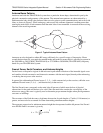
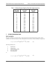
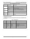
RSSI Monitoring Interface
The RSSI voltage is a function of the signal strength at the receiver and is used to measure the received
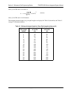
signal strength. RSSI varies from approximately 0 to 5 VDC. An RSSI calibration sheet is shipped with the
system to provide the installer a cross-reference between actual received signal level (in dBm) and RSSI
voltage. This sheet is useful for verifying link budget calculations and ensuring proper equipment
installation.
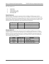
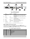
Front Panel LEDs
With the TRACER powered-on, the front panel LEDs provide visual information about the status of the
system. Table 2 describes the LEDs.
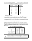
Table 1. TRACER 64x0 Front Panel Description
1
1 Detailed discussions (including pinouts) of front panel components (where applicable) follow the table.
Name Connector Description
A
RSSI bantam DC voltage indicating strength of the received signal at
the antenna
B
Status LEDs N/A Visual status information about the system
C
GND bantam Ground reference for the RSSI interface
D
TEST 3.5 mm mini-jack Factory use only
E
AUX RS232 RJ-45 Serial interface for a 9600 bps connection between the
local and remote systems over the RF link
F
CRAFT PORT DB-9 RS-232 interface for connection to a VT100 terminal or
PC with terminal emulation software
Table 2. TRACER 64x0 LEDs
For these LEDs... This color light... Indicates that...
PWR Green (solid) the TRACER is connected to a power source.
Off the TRACER is not currently powered up.
TEMP
*TRACER 64x0 high
power system only
Green (solid) the TRACER 64x0 high power system temperature is within
normal range.
Red (solid) the TRACER 64x0 high power system has an active temperature
alarm.
FAN
*TRACER 64x0 high
power system only
Green (solid) the TRACER 64x0 high power system fans are working properly.
Red (solid) the TRACER 64x0 high power system fans are not functioning.
TST
*TRACER 6420 (L1) only
Amber (flashes once) power-up self-test is in progress. If the LED continuously flashes
or remains on (solid) after 10 seconds, the unit has failed
self-test.