


TRACER 6000 Series Integrated System Manual Section 5 User Interface Guide
612806420L1-1F Copyright © 2005 ADTRAN, Inc. 75
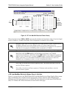
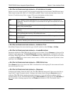
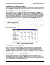
>T1X STATUS/CONFIGURATION/LOOPBACK > T1X INTERFACE ALARMS
Displays any active alarms on the T1 link (reported from both the local and remote TRACER 64x0 units).
These alarms include Red, Blue/AIS, Yellow, LOS, and bipolar violations (BPV). Table 2 briefly describes
these alarms. See Section 8, Troubleshooting Guide, on page 125 for more information on these alarms.
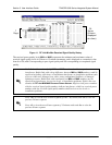
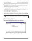
> T1X STATUS/CONFIGURATION/LOOPBACK > ALARM REPORTING
Determines whether the TRACER 64x0 unit will report active alarms. If set to DISABLED, no alarms will be
displayed on this menu page. The
ALARM REPORTING parameter is independently configured for the local
and remote TRACER 64x0 units. When set to
DISABLED, the TRACER 64x0 does not report active alarms
via SNMP or the
CRAFT port, and the status LEDs are off. By default, alarm reporting is set to ENABLED.
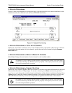
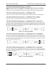
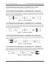
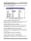
>T1X STATUS/CONFIGURATION/LOOPBACK > T1X LINE BUILD OUT
Configures the T1 for the appropriate line build out, based on the distance to the T1 equipment. By default,
the line build out for the TRACER 64x0 is
0 dB/133 FT.
> T1X STATUS/CONFIGURATION/LOOPBACK > SIGNALING
Configures the framing format for the T1 link for both the local and remote TRACER 64x0 units. The
TRACER 64x0 transports T1 data across the link (as long as the T1 signal is properly timed). Configure
the framing format (using the
SIGNALING menu) to enable the TRACER 64x0 to monitor incoming framing
error events and indicate problems with the attached metallic service. The TRACER 64x0 supports both
extended superframe (
ESF) and superframe (D4) framing formats. By default, the signaling method is set
to
ESF.
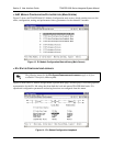
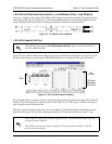
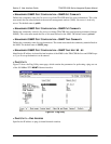
> T1X STATUS/CONFIGURATION/LOOPBACK > LINE CODE
Sets the line coding for the T1 link. The TRACER 64x0 supports bipolar eight-zero substitution (B8ZS)
and alternate mark inversion (AMI) line coding. By default, the line code is set to B8ZS.
> T1X STATUS/CONFIGURATION/LOOPBACK > LOOP/NORMAL STATE
Controls the loop status of the T1 link. Activates/deactivates loopback conditions for testing purposes.
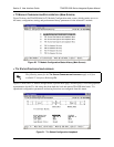
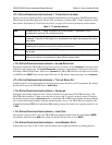
Table 2. T1 Interface Alarms
RED Activates when no T1 signal is present from the connected T1 equipment. LOS is
activated after receiving 192 consecutive zeros.
BLUE/AIS (Alarm Indication Signal) Activates when an incoming remote alarm is received from a
connected T1 device. An AIS signal is an unframed all one signal that replaces the normal
traffic signal.
YEL (Yellow Alarm) Activates when an incoming remote alarm is received from the T1 device
indicating that a failure has occurred in the received direction.
LOS (Loss of Sync) Occurs when the TRACER system cannot synchronize to the incoming T1
data stream.
BPV (Bipolar Violations) Activates when the incoming T1 stream presents BPVs. BPVs occur
when two one bits are received back-to-back with the same polarity.