


TRACER 6000 Series Integrated System Manual Section 4 Network Turnup Procedure
612806420L1-1F Copyright © 2005 ADTRAN, Inc. 47
5. GROUNDING INSTRUCTIONS
The following paragraphs provide grounding instruction information from the Underwriters’ Laboratory
UL60950 Standard for Safety of Information Technology Equipment Including Electrical Business
Equipment, with revisions dated March 15, 2002.
An equipment grounding conductor that is not smaller in size than the ungrounded branch-circuit supply
conductors is to be installed as part of the circuit that supplies the product or system. Bare, covered, or
insulated grounding conductors are acceptable. Individually covered or insulated equipment grounding
conductors shall have a continuous outer finish that is either green, or green with one or more yellow stripes.
The equipment grounding conductor is to be connected to ground at the service equipment.
The attachment-plug receptacles in the vicinity of the product or system are all to be of a grounding type, and
the equipment grounding conductors serving these receptacles are to be connected to earth ground at the
service equipment.
A supplementary equipment grounding conductor shall be installed between the product or system and
ground that is in addition to the equipment grounding conductor in the power supply cord.
The supplementary equipment grounding conductor shall not be smaller in size than the ungrounded
branch-circuit supply conductors. The supplementary equipment grounding conductor shall be connected to
the product at the terminal provided, and shall be connected to ground in a manner that will retain the ground
connection when the product is unplugged from the receptacle. The connection to ground of the
supplementary equipment grounding conductor shall be in compliance with the rules for terminating bonding
jumpers at Part K or Article 250 of the National Electrical Code, ANSI/NFPA 70. Termination of the
supplementary equipment grounding conductor is permitted to be made to building steel, to a metal electrical
raceway system, or to any grounded item that is permanently and reliably connected to the electrical service
equipment ground.
The supplemental grounding conductor shall be connected to the equipment using a number 8 ring terminal
and should be fastened to the grounding lug provided on the rear panel of the equipment. The ring terminal
should be installed using the appropriate crimping tool (AMP P/N 59250 T-EAD Crimping Tool or
equivalent).
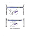
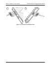
The supplemental equipment grounding terminal is located on the rear panel of the
TRACER 64x0.
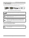
When using a power source that has the positive terminal or the negative terminal
connected to earth ground, the grounded terminal must be attached to the TRACER 64x0
power input that is identified with the ground symbol. Otherwise, equipment damage will
occur. When using a power source that has neither terminal connected with earth ground
(floating), either terminal may be connected to the TRACER 64x0 power input identified
with the ground symbol.