


Section 3 Engineering Guidelines TRACER 6000 Series Integrated System Manual
32 Copyright © 2005 ADTRAN, Inc. 612806420L1-1F
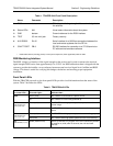
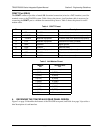
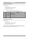
AUX RS232 Interface (RJ-45)
The AUX RS232 interface provides a female RJ-45 terminal connection (wired as a DCE interface), used
for a 9600 bps point-to-point connection between the local and remote systems (over the RF link). Table 3
shows the pinout.
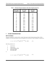
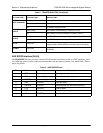
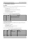
STATUS
MOD1 and MOD2
Green the module is installed and functioning properly.
Red (solid) a port on the installed module is currently in alarm.
Off no module occupies the slot.
PLAN A
Green (solid) the TRACER is transmitting on Frequency Plan A.
Off the TRACER is not transmitting on Frequency Plan A.
PLAN B
Green (solid) the TRACER is transmitting on Frequency Plan B.
Off the TRACER is not transmitting on Frequency Plan B.
RF LO Red (solid)
the RSSI level is below suggested minimum threshold
(approximately 10 dBm above the minimum receive sensitivity).
RF DWN Red (solid)
there is a communication problem between the local and remote
TRACERs.
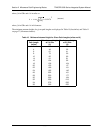
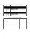
Table 3. AUX RS232 Pinout
Pin Name Source Description
1 GND Common Signal ground
2 RTS Attached Equipment Request to send (unused)
3 TXDATA Attached Equipment Transmit data (from attached equipment)
4 DSR TRACER Data set ready
5 RXDATA TRACER Received data (to attached equipment)
6 CTS TRACER Clear to send
7 DTR Attached Equipment Data terminal ready (unused)
8 CD TRACER Carrier detect
Table 2. TRACER 64x0 LEDs (Continued)
For these LEDs... This color light... Indicates that...