


Section 4 Network Turnup Procedure TRACER 6000 Series Integrated System Manual
44 Copyright © 2005 ADTRAN, Inc. 612806420L1-1F
1. INTRODUCTION
This section discusses TRACER 64x0 system installation.
2. TOOLS REQUIRED
The tools required for TRACER 64x0 installation are:
• VT100 terminal or PC with terminal emulation software
• RS-232 (DB-9 male for TRACER 64x0) cable for connecting to terminal
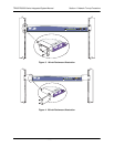
3. UNPACK AND INSPECT THE SYSTEM
Each TRACER 64x0 is shipped in its own cardboard shipping carton. Open each carton carefully and
avoid deep penetration into the carton with sharp objects.
After unpacking the unit, inspect it for possible shipping damage. If the equipment has been damaged in
transit, immediately file a claim with the carrier; then contact ADTRAN Customer Service (see Warranty,
Customer Service, Product Support Information, and Training information in the front of this manual).
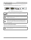
Contents of Shipment
Your shipment of the base unit includes the following items:
• TRACER 64x0 unit
• RJ-45 to DB-9 connector (ADTRAN P/N 3196ADPT001) for connection to the AUX RS232 port
• 6-foot silver satin cable for connection to the AUX RS232 port
• Rackmount brackets
• Power and Alarm connectors
• Spare fuse
• ADTRAN received signal power versus RSSI reference sheet
• TRACER 64x0 Documentation CD
Changes or modifications not expressly approved by ADTRAN could void the user’s
authority to operate the equipment.
To prevent electrical shock, do not install equipment in a wet location or during a lightning
storm.
This system MUST be installed by qualified service personnel in a Restricted Access
Location.