


Section 2 Microwave Path Engineering Basics TRACER 6000 Series Integrated System Manual
18 Copyright © 2005 ADTRAN, Inc. 612806420L1-1F
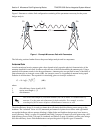
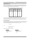
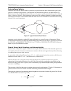
Figure 1 illustrates a wireless link configuration containing all the parameters necessary for the power
budget analysis.
Figure 1. Example Microwave Path with Parameters
The following sections further discuss the power budget analysis and its components.
Antenna Gain
Actual transmit and receive antenna gain values depend strictly upon the physical characteristics of the
antennas installed for each link. In other words, the size of the dish determines the antenna gain. Using a
parabolic dish antenna results in the best performance. Antenna gains are specified in terms of decibels of
gain referenced to an isotropic source (dBi). An isotropic source is a hypothetical antenna having equal
radiation in all directions. The equation for calculating gain over isotropic radiation is
where
k dish efficiency factor (usually 0.55)
λ carrier wavelength (c / f)
D dish diameter
The dish efficiency factor (k) is used to estimate how efficiently the dish reflector passes energy to the
feedhorn. The “standard” factor is 0.55 (measured performance of prime-focus dishes with a pyrimidal
waveguide feedhorn with no aperture blockage). Other dishes and feedhorn designs may have better or
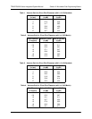
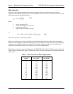
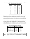
worse efficiency. Table 1 on page 19 (standard) and Table 2 on page 19 (metric) provide gains using a 0.55
dish efficiency factor. Table 3 on page 19 (standard) and Table 4 on page 19 (metric) provide gains using a
0.40 dish efficiency factor. Dish manufacturers can provide gains for specific types of antennas.
The carrier wavelength (λ) and dish diameter (D) can be metric or standard units of
measure. Use the same unit of measure for both variables. For example, a carrier
wavelength of 0.124 meters requires a dish diameter in meters as well.
G
T
G
R
d, L
P
P
T
P
R
λ
L
L
G 10 log k
π D⋅
λ
------------
⎝⎠
⎛⎞
2
⋅
⎝⎠
⎜⎟
⎛⎞
⋅=
(dBi)