


Section 2 Microwave Path Engineering Basics TRACER 6000 Series Integrated System Manual
24 Copyright © 2005 ADTRAN, Inc. 612806420L1-1F
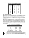
6. ANTENNA INFORMATION
The overall wireless system is directly affected by the antenna selection and installation, discussed in the
following sections.
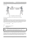
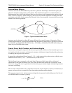
Antenna Alignment
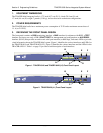
With line-of-sight microwave communications, optimum system performance requires that the
transmitting and receiving antennas are properly aligned. This ensures maximum received signal power at
each receiver. Antenna alignment must be achieved in both azimuth (along a horizontal plane) and
elevation (along a vertical plane). By ensuring maximum received signal strength, a received signal
strength indicator (RSSI) helps the equipment installer determine when alignment is maximized.
TRACER RSSI Test Points
RSSI for the TRACER 64x0 system is provided through the VT100 terminal menus accessed through the
RS-232 interface, and it is presented as a series of bars indicating signal strength. More bars means more
RSSI, which ensures greater received signal strength and better link performance.
If both the local and remote end of the system are operational, the remote TRACER 64x0 receive power
can be viewed from the local TRACER 64x0 VT100 terminal menu interface.
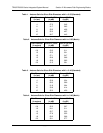
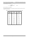
An RSSI test point located on the front panel provides a DC voltage level (relative to the
GND test point)
that corresponds to the amount of signal being received from the far end’s transmitter. The voltage at this
test point can vary from approximately 0 to 5 VDC. An RSSI calibration sheet is shipped with the system
to provide the installer a cross-reference between actual received signal level (in dBm) and RSSI voltage.
This sheet is useful for verifying link budget calculations and ensuring proper equipment installation.
Real-time Signal Values
The TRACER 64x0 system displays real-time signal values for RX QUALITY, RX POWER, and TX POWER
(for both the local and remote units).
RX QUALITY values are displayed as a numerical value from 0 to 100,
with 0 corresponding to poor signal quality and 100 corresponding to exceptional signal quality.
RX POWER values are displayed in dBm within ±5 dBm accuracy and can vary with extreme temperatures.
TX POWER values are displayed in dBm within ±1 dBm accuracy.
Verify the antenna installation meets all regulations specified in the National Electric
Code (NEC) Article 810 with particular attention to clearances from power and lighting
conductors, mounting, grounding, and antenna discharge unit.
Real-time signal values are not supported on all TRACER 64x0 systems. Systems must be
ADTRAN calibrated to provide readings for Rx or Tx Power signal levels.