


Section 4 Network Turnup Procedure TRACER 6000 Series Integrated System Manual
50 Copyright © 2005 ADTRAN, Inc. 612806420L1-1F
8. INSTALLING MODULES
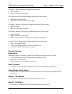
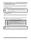
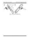
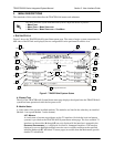
Figure 5 shows the slot numbering designation as viewed from the rear of the TRACER 64x0. The
functionally identical option slots only accept TRACER 6000 Series modules.
Figure 5. TRACER 64x0 Network Module Slot Designation
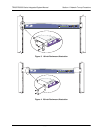
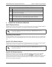
Instructions for Installing Network Modules
Individual access modules insert in the back of the chassis. Two phillips-head screws hold the modules in
place for added security. To install network modules, follow the steps outlined in the following table.
Access modules are intended to be serviced by qualified service personnel only.
TRACER 64x0 modules are not hot swappable. Remove power from the system before
installing or removing the module.
Electronic modules can be damaged by static electrical discharge. Before handling
modules, put on an antistatic discharge wrist strap to prevent damage to electronic
components. Place modules in antistatic packing material when transporting or storing.
When working on modules, always place them on an approved antistatic mat that is
electrically grounded.
For proper airflow through the system to avoid elevated temperature levels, leave filler
plates on any unused slots.
MODULE 1 MODULE 2